HITEC Optic 6 User Manual
Page 14
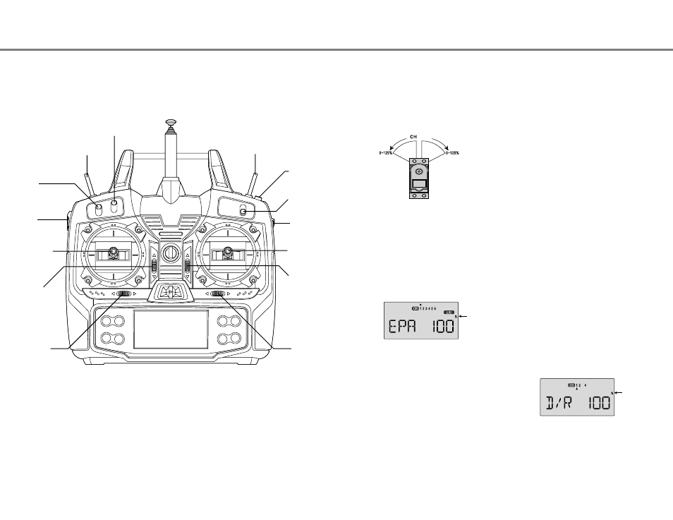
This figure shows the assignments for a Mode 2 system as supplied by the factory.
Note that some of the functions will not operate until activated in the mixing menus.
The EPA function is used to set (or limit) the travel of each
servo, and may be set anywhere from 0% and 125% for each
travel direction. Reducing the percentage settings reduces the
total servo throw in that direction. The EPA function is normally
used to prevent any servos from binding at the ends of their
travel. If you change the EPA setting to 0%, you will not
have any servo response in that direction, and will
probably crash.
1. Enter the programming mode by pressing the two Edit Up
Down keys (the two keys on the far left) at the same time.
You should pop right into the EPA screen, but if you do not,
press either Edit Up Down key until you see EPA displayed.
The channel indicator is above numeral 1 for ailerons, the
percent symbol will be flashing, and you'll notice that you
can change the L/U indicator to R/D (or vice versa) by
moving the aileron (right) stick. In the next steps you will
see how you set the travel directions independently for each
stick (or lever or gear switch) motion.
2. To set the RIGHT aileron servo travel, move the aileron stick
all the way to the right and hold it. The letters "R/D" should
appear next to the flashing percent sign, meaning you are
setting either Right or Up travel (with ailerons it's right or left
only, but the display is set up to use the same indicators for
elevator and throttle, thus the dual meanings for the letters).
Now if your servo is stalled or binding, you'll hear a buzzing
sound. Hit the Data -Decrease key until the buzzing stops.
If the servo is not buzzing, leave the setting at 100%. Later,
depending on how rapidly the model rolls, you can use
aileron dual rates to reduce the sensitivity.
3. To set the LEFT aileron motion, move the aileron stick all the
way to the left and hold it. The letters "L/U" should appear
next to the flashing percent sign. Again listen and hit the
Data -Decrease key until the buzzing stops. If the servo is
not buzzing, leave the setting at 100%.
4. To set EPA travel for other channels, press the Cursor Right
key to select the channel you wish to change. The little
triangle moves and indicates the active channel. Repeat
these steps with each channel in sequence, taking care to
set the travel for both directions. You may set each channel
separately, anywhere in between 0% and 125%, and if you
wish to rapidly return to the default 100% setting, press the
Active/Inhibit (Clear) key.
5. Return to the regular operating mode by pressing the two
Edit Up Down keys simultaneously.
If this is your first computer radio, you may have never been
introduced to dual rates before. Dual rates are used because
most models respond more rapidly to control inputs while
they're flying at higher speeds, and it is possible to be really
gentle with the controls and yet still over-control. Dual rates are
used to adjust the transmitter so that a control actuated at high
speed will not cause a radical response, so they are very useful
for beginning pilots as well as experts.
Dual rates are selected by flipping the dual rate switches on the
transmitter. The Optic has two dual rate switches, one for
ailerons and one for elevator, and rudder. The aileron dual rate
switch is located over the right-hand stick; the elevator and
rudder dual rate switch is located over the left-hand stick. The
amount of travel reduction or increase may be set anywhere
between 0 and 125%.
Note: if you set the dual rate amount to zero,
you will get no response from that channel, which may cause a crash.
1. Get to the D/R screen with the Edit Up Down keys.
2. The active channel number is indicated by the arrow above
or below the channel numbers. The arrow's position
depends on the position of that channel's dual rate switch.
In the figure, the aileron (CH1) dual rate setting at the D/R
switch's lower position is being programmed.
Optic Aircraft Controls and Switch Assignments
Airplane Model Function Descriptions
EPA - End Point Adjust
D/R - Dual Rates
Setting EPA values on your system:
Inputting Dual Rate Values
Airplane Model Function Descriptions - Page 27
Optic Aircraft Controls and Switch Assignments - Page 26
Trainer Switch
Engine Cut
Switch
SW3
Aileron Dual
Rate Switch
FLIP TRIM
SW1
Electric Motor On/Off
Elevator / Rudder D/R
Aux
(ch-6:flap adj)
Crow Activate
Rudder -
Throttle Stick
Aileron &
Elevator Stick
Throttle
Trim Switch
Elevator
Trim Switch
Rudder
Trim Switch
Aileron
Trim Switch
SW2
Aux(ch-5:gear)
Crow ON/OFF
SW4
Elevator to Flap Mix
Camber mix
(Landing mix)
49
Flashing
Flashing