Helicopter setup instructions – HITEC Optic 6 User Manual
Page 24
Helicopter Setup Instructions
Helicopter Setup Instructions
The following example shows how the Optic may be programmed for a helicopter model.
Your model's settings will be dependent on the setup and linkages.
If you're not sure about the settings for your particular model, please ask an experienced pilot for assistance.
The helicopter setup procedure presented below uses a
standard helicopter setup, one servo each for ailerons and
elevator. You can use a similar procedure to set up your own
model; your setting's numbers and percentages will probably
be different.
1. In the helicopter, install each servo and hook up the aileron,
elevator, throttle, rudder, and collective pushrods to the
servos in accordance with the model's instructions or plans.
Be sure that all of your servos are plugged into the proper
receiver channels:
CH1 - Aileron (Roll Cyclic)
CH2 - Elevator ( Pitch Cyclic)
CH3 - Throttle
CH4 - Rudder (Gyro Yaw control)
CH5 - Gyro (For gyro gain control)
CH6 - Pitch ( Blade Collective)
If your model uses 120° swash programming, plug in the
servos as indicated in the table on page 9.
We recommend that you do this programming exercise with
the servos installed in the model and connected to the
respective control surfaces. This will enable you to
immediately see the effect of each programming step.
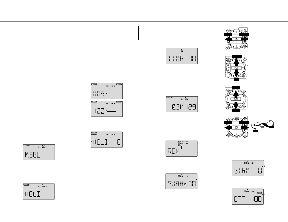
2. Model Memory. Turn on your transmitter while holding the
two Edit Display keys. This gets you into the model select
(M.SEL) menu. Press the Cursor Right button to move to a
new model memory. The model number of the model
memory you select is indicated by the little arrow pointing
down. The figure shows Memory #4.
4. Swash Type. Now it's time to select the swash type. Select
NOR for helis with independent aileron, elevator, and pitch
servos; 120' for models using 120° swashplates. Press
the Up Edit arrow until you see the word "SWASH" in the
upper right of the display. The swash type in the lower left
will be flashing.
5. Name your model. Press the UP arrow once. This gets
you into the model name mode (note the words MODEL and
NAME in the upper left of the display).
6. Now you can select four letters to identify your model. With
the first of the four letters flashing, press the Data +Increase
or -Decrease keys to change the letter that is displayed.
Stop when the first letter is the one you want.
7. Press the Right Cursor key once to get to the second letter.
Repeat Step 5 to choose the second letter.
8. Repeat the previous steps two more times to fill out the
remaining two letters. If you like, you can hit the right cursor
button one more time and select a number between 0 and
199 for further identification. The model's frequency number
might be a good choice.
3. Model Type. Press the UP Edit arrow two times. The word
ACGL will appear, flashing on and off. Press the Left or
Right Cursor keys until HELI appears. You must press both
Data keys to "Save" the setting. This is how you select the
type of model you wish to use, either ACGL or HELI.
WARNING: selecting a different model type will erase the settings in
the model memory. BE SURE you're in the correct model
memory before selecting a new model type, or you might
accidentally erase a model you're using.
Flashing
Flashing
Flashing
Helicopter Setup Instructions - Page 46
Helicopter Setup Instructions - Page 47
9. Set the stopwatch. Press the Down arrow four times. This
gets you into the Timer menu (TIME). Use the Data Increase
and Decrease keys to select the amount of time you want the
stopwatch to count down. This is handy to keep track of
engine running time so you don't run out of gas. You can set
a second timer for a different amount of time.
10. This completes the initial part of the setup. Now, we'll go
ahead and customize the settings for your model. Switch
transmitter power OFF.
11. Switch transmitter power back on and transmitter should
display the model number and battery voltage as shown.
The number on the right is the elapsed time, which will vary
depending on how long the transmitter has been left on.
12. Servo Directions. Check the proper direction of throw for
each servo. Use the reversing function [REV] to reverse
channels as necessary to get proper throw directions. If
you're using the 120° swashplate, please read the SWAH
menu instructions on page 53 to see how your model
responds to the different commands.
14. Servo Neutrals. First, be sure the hovering pitch and
hovering throttle levers on the sides of the radio are
centered. Set up all linkages so that all servos are as close
(STRM) window to make fine adjustments on the servo
neutrals.
15. Servo Travel. Use the EPA command to limit servo travels
to prevent binding.
13. If you're using 120° swash type, please use the
swashplate (SWAH) menu, page 53, to adjust these
responses.
LEFT
RIGHT
LEFT
RIGHT
LEFT
RIGHT
DOWN
UP
HIGH
LOW
Right Aileron:
swashplate tilted
towards chopper's
right side.
Left Aileron:
swashplate
tilted towards the
left side.
HIGH Position:
high rotor pitch
AND carburetor
fully opened.
LOW Position:
low rotor pitch,
carburetor at idle
(use trim tab to
fully close)
Down Elevator:
swashplate tilted
towards chopper's
front.
Up Elevator:
swashplate
tilted towards the
rear.
NAME
Flashing
Flashing
Flashing
"H" Only.
Flashing "1"
Flashing