Airplane model function descriptions, Aircraft flight trimming chart – HITEC Optic 6 User Manual
Page 21
Airplane Model Function Descriptions
Airplane Model Function Descriptions
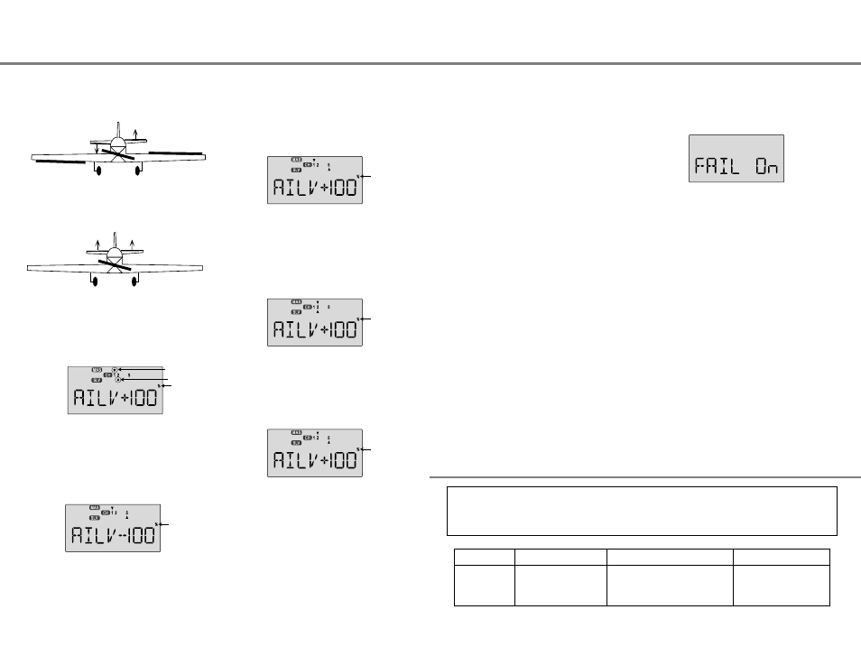
3. Move the stick to command aileron. In addition to the aileron
servo(s), both elevator servos should move. They may move
in opposite directions (as they should) or the same direction
(instructions for correcting this are below).
4. Move the stick to command elevator. Both elevator servos
should move. They may move in the same direction (as
they should) or opposite directions (to be corrected below).
5. Press the Cursor Right key to get to the travel setting
menus. The display shows a triangle over the number 1 and
under the number 2, indicating you are in the AIL->CH2
setting menu, programming the response of the CH2
elevator servo due to aileron (CH1) commands.
6. If the elevator servo plugged into CH2 goes the correct
direction with aileron stick, go to the next step. Otherwise,
press the Data +Increase or -Decrease keys to change the
sign of the percentage displayed. If it is (+), change it to (-),
or vice versa. Only change the sign of the number, you can
decrease its value later if you need to.
7. If the elevator servo plugged into CH5 goes the correct
direction with aileron stick, go to the next step. Otherwise,
press the Cursor Right key to get to the AIL->CH5 setting
menu, then press the Data +Increase or -Decrease keys to
change the sign of the percentage displayed. If it is (+),
change it to (-), or vice versa. Only change the sign of the
number, you can decrease its value later if you need to.
8. If the elevator servo plugged into CH2 goes the correct
direction with elevator stick, go to the next step. Otherwise,
press the Cursor Right key to get to the AIL->CH2 setting
menu, then press the Data +Increase or -Decrease keys to
change the sign of the percentage displayed. If it is (+),
change it to (-), or vice versa. Only change the sign of the
number, you can decrease its value later if you need to.
9. If the elevator servo plugged into CH5 goes the correct
direction with elevator stick, go to the next step. Otherwise,
press the Cursor Right key to get to the ELEV->CH5 setting
menu, then press the Data +Increase or -Decrease keys to
change the sign of the percentage displayed. If it is (+),
change it to (-), or vice versa.
Airplane Model Function Descriptions - Page 40
Airplane Model Function Descriptions - Page 41
10. Once you have all the servos moving the correct directions,
you can go back and adjust each of the travels
independently, so that both elevator servos move up the
SAME amount when elevator control is given, and move
opposite the same amount for aileron command. You will
need to decrease the percentage shown for the one moving
further, or increase the percentage for the one moving less.
FAIL - Failsafe Function
Setting Up the FAILSAFE Function
QPCM Operation
Activating the Hitec QPCM Failsafe
The failsafe feature of Hitec's QPCM receiver, model number
HPD-07RH is a safety feature designed to allow the user to
program a "set" position for a flight control surface to be at,
in the event of a loss of signal from the transmitter.
Your Optic system contains special programming to allow you
to fly a model using Hitec's special QPCM software. In this
menu, which only appears when QPCM is selected in the
power-on menus, you can choose where your servos are
commanded to move if the receiver loses the signal from the
transmitter due to interference.
Note: The OPTIC 6 QPCM is NOT compatible with Hitec's older
HPD-07RB PCM receivers and must be used with Hitec's
HPD-07RH QPCM receiver.
Note: Failsafe does not have to be activated to use the QPCM signal.
You do have the choice of using or not using the failsafe function.
1. To access this screen, turn on the transmitter.
2. Turn on the receiver power.
3. Press both Edit keys at the same time enter the menu loop.
4. Use the Edit keys to scroll down or up through the menu
until you come to the Failsafe screen.
5. The default position has the failsafe feature inhibited.
6. Arm the failsafe feature by pressing the "Clear" key, the
screen should now read, FAIL On.
7. To set the desired servo position when failsafe lockout
occurs, move the control sticks to the position you want the
control surfaces to be in if a failsafe condition should occur,
hold the sticks in this position and press both Data keys at
the same time. You should hear a double "beep"
8. Cycle the transmitter on, then off, then back on.
9. Test the effect by turning off your transmitter and watching
the servo failsafe position activate.
10. To change the failsafe hold positions, repeat step
7, 8 and 9.
Aircraft Flight Trimming Chart
The following chart may be used to systematically set up and trim a model for straight flight and aerobatic maneuvers.
Please note that for best results, trimming should be done in near-calm conditions. Before you decide to make a change,
be sure to try the test several times before making adjustments. If any changes are made, go back through the
previous steps and verify that they are not also affected. If they are, make further adjustments as necessary.
1. Control
neutrals
Fly the model straight and
level
Use the transmitter trims for hands-off
straight & level flight.
Change electronic subtrims
or adjust clevises to center
transmitter trims.
To test for...
Test Procedure
Observations
Adjustments
Master control
Slave Ch.
Flashing
Flashing
Flashing
Flashing
Flashing