Airplane model function descriptions – HITEC Optic 6 User Manual
Page 20
Airplane Model Function Descriptions
Airplane Model Function Descriptions
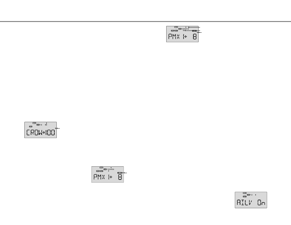
PMX1, PMX2 - Programmable Mixes 1 and 2
Your Optic system contains TWO independent programmable
mixers (PMX1 and PMX2) with unique capabilities. You may
use mixing to correct unwanted tendencies of the aircraft during
aerobatics, takeoff, or landing, or some special maneuver of
your own choosing. Each mixer may be programmed to do
things that are not built-in programs. This makes them useful
for all sorts of different things. Note that the mixers may be
programmed to be turned on by flipping a selected switch, or
to be on all the time.
You may also use the mixers for correcting unwanted flying
tendencies, like automatically applying a bit of rudder with
throttle to account for torque/P-factor effects, to a corrective
elevator motion during knife-edge flight to correct for an
undesired tucking tendency (the latter is described in the
ACGL model setup section and below).
1. Call up the mixer screen by repeatedly pressing one of the
Edit Up Down keys until a PMX window appears. The
default is for the function to be inhibited. To activate, press
the Active/Inhibit (Clear) key. This will cause the INH
display to change to a display showing 100%, Master and
Slave indicators, and a flashing ON or OFF depending on
the position of the ON-OFF switch that is selected. See the
Switch Select instructions on P. 39 for information on how to
Using the Programmable mixers
8. If you can't get enough travel, go to the EPA menu and be
sure channel 6 is set as high as possible to get 90° flap
travel. Of course, you can reduce them to get the amount of
travel that you'd like at full crow in the EPA menu, but this is
better done in the Crow menu as given in the previous step.
It may be helpful to use long servo arms on the flap servos
to increase their effective throw.
For starters, use zero or very little elevator compensation
until you fly and determine what is needed: if the model
pitches up with crow, add down elevator compensation and
if it pitches downwards, add some up compensation. Make
only small changes in compensation because it has a big
effect on trim.
Remember to try your crow setup out at higher altitudes to
verify that the trim doesn't change rapidly. If you want to
steepen the descent, increase the flap downward deflection
while increasing the up aileron movement.
Caution: when setting up crow, do not call for too much aileron "up"
travel, or you'll lose roll authority, and this occurs at a crucial
time, when your model is flying relatively slowly on a landing
approach. Always make changes in small increments, don't
try to do it "all at once."
Airplane Model Function Descriptions - Page 39
Airplane Model Function Descriptions - Page 38
5. Now press the Cursor right key one time to get to the
elevator setting menu (a small arrow will appear over the
number 2 in the display). Press the Data +Increase or
-Decrease keys to set up the throws for the elevator as
desired. Move the left lever and be sure the elevator goes
down with crow. If it doesn't, change the sign (this may
depend on servo orientation). You probably should not use
much elevator motion until you determine if Crow changes
the trim.
6. Now press the Cursor right key one time to get to the
second aileron setting menu (a small arrow will appear over
the number 5 in the display). Press the Data +Increase or
-Decrease keys to set up the throws for the second aileron
as desired. Move the left lever and be sure the second
aileron goes UP with crow. If it doesn't, change the sign
(this may depend on servo orientation). Be sure to set both
aileron offsets to be the same.
7. Now press the Cursor right key one time to get to the flap
menu (a small arrow will appear over the number 6 in the
display). Press the Data +Increase or -Decrease keys to set
up the throws for the flaps as desired. Move the Left lever
and be sure the flaps go down with crow. If they don't,
change the sign (this may depend on servo orientation).
You'll probably want as much flap motion as possible - 90 is
great if you can get it. Like the ailerons, you set both flap
offsets at the same time.
select the ON-OFF switch. Be sure the PMIX is ON so you
can see the results of your programming. The default switch
for PMIX 1 is SW-3 and default for PMIX 2 is SW-1.
2. Now you'll select the Master channel for the mixing, the
channel that causes the mixing to occur. Press the Cursor
Right key to get the master channel indicator MAS flashing
on and off, then press the Data +Increase or -Decrease
keys to move the top arrow over the number of the desired
master channel, 1 - 6.
Master
Slave
3. Next you'll put in the Slave channel, the one that is affected
by motion of the master channel. Press the Cursor Right
key to get slave channel indicator SLV flashing on and off,
then press the Data +Increase or -Decrease keys to move
the bottom arrow underneath the number of the desired slave
channel.
4. Now you'll input the mixing percentage, which tells how much
the slave channel responds to the master channel. Press the
Cursor Right key to cause the percent (%) sign to the right of
the large number to flash on and off. Note that you can set
the percentage for the mixer on each side of the master
channel's control's motion by moving the master channel's
control back and forth. The motion of the master channel's
control is also indicated by the R/D (= Right/Down) or L/U
(= Left/Up) indicator in the window.
5. Hold the master channel's control to one side, and then use
the Data +Increase or -Decrease key to change the
percentage for the mixer. Verify that you get the proper
motion of the slave channel when you move the master.
If you don't get a response to the master movement,
check that the mixer is turned on with its on-off switch.
Change the percentage if the amount of travel is incorrect.
If you want to set the percentage to ZERO, press the
Active/Inhibit (Clear) key.
6. Move the master control to the other side of its travel and
then repeat the actions in the previous step to set the
amount of mixing on the other side. Use the Data +Increase
or -Decrease key to change the percentage for the mixer
until you get the response you want for the second side.
[Knife-Edge Example: for a model that tucks during knife-edge
flight, set up a mixer with Master = 4 (Rudder), and Slave = 2
(elevator). You want to get up elevator mixed in for either
direction of full rudder. Therefore, you'll set plus mixing on one
side of the rudder stick, and minus mixing on the other side.
Normally only 5% to 10% mixing is needed to solve this problem.
S/W SEL - Switch Selection For Auxiliary Functions
Your Optic system allows you to customize your radio and
choose what switches are used to turn on the following
functions: A->R, E->F, CAMB, CROW, LAND, PMX1, and
PMX2. Note that each of these functions may be chosen to be
turned on by flipping a switch, or to be on all the time.
AILV - Ailevator Function
Choosing The On-Off Switch For Certain Radio Functions
1. Call up the Switch Select screen by repeatedly pressing one
of the Edit Up Down keys until the highlighted words S/W
SEL appear. The window may appear with any of the
following displayed: A->R, E->F, CAMB, CROW, LAND,
PMX1, and PMX2.
2. Use the Data +Increase or -Decrease keys to select the
desired function.
3. Use the Left Right Cursor keys to select from the following
on-off possibilities for the selected function
a. On indicates the function is ALWAYS on.
b. 1 represents Switch SW-1, the "ELEV RUDD D/R"
switch. On is down.
c. 2 represents Switch SW-2, the "GEAR AUX" switch.
On is down.
d. 3 represents Switch SW-3, the "AIL D/R" switch.
On is down.
e. 4 represents Switch SW-4, the "FLT MODE" switch.
The FLT MODE switch has three positions to
select from:
i. NOR = on at forward position
ii. ST1 = on at middle position
iii. ST2 = on at aft position
4. Repeat Steps 2-3 for any additional functions you wish to set.
Your Optic system contains special programming to allow you
to fly a model with two independent elevator servos which
respond together to the elevator stick, and in opposite
directions to the aileron stick. This combination of aileron and
elevator results in the name "ailevator" and allows you to do
torque rolls with 3-D aircraft! Note that the AILV function is on
all the time once it is activated.
Setting Up the Ailevator Function
1. This function requires two elevator servos, one for each side.
Plug the right elevator servo into channel 2, and the second
elevator servo into channel 5. If you need retracts, you will
have to use the output from channel 6.
2. Call up the mixer screen by repeatedly pressing the Edit Up
or Down key until the AILV window appears. The default is
for the function to be inhibited. To activate, press the
CLEAR key. This will cause the AILV INH display to change
to AILV ON. AILV is not a switch able function, it is either
ON or OFF.
Flashing
Flashing
Flashing