Helicopter setup instructions, Menu descriptions - helicopter – HITEC Optic 6 User Manual
Page 25
Helicopter Setup Instructions
Helicopter Setup Instructions
19. Throttle Curve. You can use the Throttle Curve (THCV)
menu's five-point setting curves to fine-tune the engine
servo's response. Adjust the throttle position for hover to
get the desired head RPM. You can change the curve
values to make a steeper curve near idle and shallower
curve past hover. See the THCV menu description on
page 52 for more details.
If your instructions don't give any suggested values,
you may start with the following settings:
Your model's instructions may provide suggested values for
the blade pitch angles. If not, you may want to start with the
following:
20. Pitch Curve. You can use the Pitch Curve (PTCV) menu's
five-point setting curves to make finer adjustments to the
endpoints and the middle of travel of the pitch servo.
After you've set the pitch at each of the five points, be sure to
check that both aileron and elevator motions do not cause
binding at extreme pitch settings. If they do, use EPA to
reduce travels.
21. Revolution mixing (RVMX) uses the tail rotor to suppress
the torque reaction of the main rotor due to changes in
collective pitch. It is disabled whenever Idle-Up, ST2,
ST3 or Throttle Hold are activated.
23. Aerobatic Setups and Flight Conditions. Your Optic
system has three built-in flight condition menus in addition
to the normal (NOR) hovering mode. Two -- ST1 and ST2
-- are typically used for aerobatics, including 540° stall turns,
looping, and rolling stall turns. ST3 is used for "throttle hold"
so that the throttle servo is disengaged during autorotations.
These functions are switched on as follows:
- NOR: ON when FLT MODE Switch is forward.
- ST1: ON, when FLT MODE Switch is centered
RVMX may be set on either side of the stick (note the letters
R/D and L/U displayed). Adjust RVMX mixing for both travel
directions as described in the trimming instructions on page 56.
Throttle Curve NOR
Pitch Curve NOR
Point
1 (low)
2
3
4
5 (high)
%
0
26
45
72
100
Point
1 (low)
2
3
4
5 (high)
Pitch
0 deg.
+5
+6.5
+8.0
+10.0
Helicopter Setup Instructions - Page 48
Menu Descriptions - Helicopter - Page 49
16. Collective Pitch. The blade collective pitch angle
(controlled by CH6 on a conventional helicopter) should
vary from -2° to +10° with full stick motion, in the "NOR"
or hovering Flt Mode. We recommend setting the hovering
pitch (pitch with throttle stick at center) to +4.5°. Adjust
servo arms and EPA values to get the desired travel at the
end points, measuring with a pitch meter.
17. Engine Servo travel. On the regular display menu, enter
a value of -25% for throttle trim. Use the EPA menu to set
up the carburetor pushrod so that at full throttle there is no
binding, and so the engine idles smoothly at low throttle.
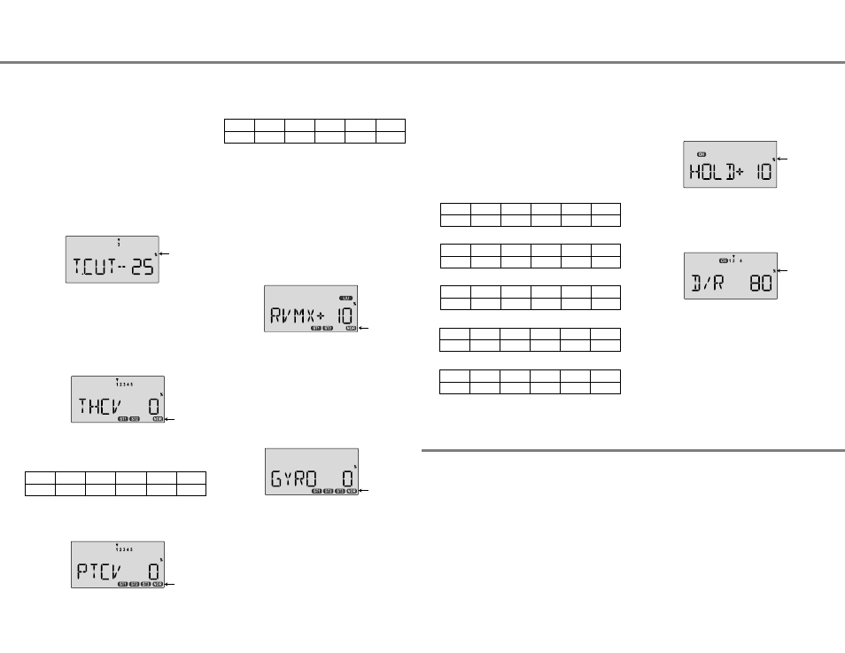
18. Throttle Cut. Enter the throttle cut (T.CUT) menu and enter
a value of -25% or so. Press the Cut button and be sure
that the carburetor fully closes, which will shut off the engine.
Don't pick too large a number, or binding may occur.
- ST2: ON when FLT MODE Switch is AFT.
- ST3: ON when ELEV RUDD D/R, SW-1 Switch is down.
As these functions are switched on or off, ST3 will override all
the others, followed by ST2 and ST1, which will override NOR.
Regular settings (NOR) occur when the others are off.
Throttle and pitch curves, revolution mixing, and gyro gain may
be independently selected for each condition.
Here are some suggested starting settings if your instructions
do not provide any:
Point
1 (low)
2
3
4
5 (high)
%
50
38
50
75
100
Throttle Curve ST2
Throttle Curve ST1
Point
1 (low)
2
3
4
5 (high)
%
100
50
38
50
100
Pitch Curve ST1
Point
1 (low)
2
3
4
5 (high)
Pitch
-4 deg.
+0.5
+6.0
+7.5
+9.0
24. Throttle Hold Setting. Throttle hold (HOLD) commands the
throttle to a preset position near idle and disconnects it
from pitch when activated. Move to the HOLD menu and
move the SW-1. switch to the forward position. Set the hold
position to maintain engine speed safely above idle without
engaging the main rotor clutch.
25. Dual Rate Settings. If you find that your aileron and
elevator controls are too sensitive, you may set dual rates
to reduce them. Use the dual rate (D/R) window to adjust
them to the desired amount of response when the switch is
flipped.
This is only a brief introduction to the setup procedure for
helicopters. Be sure to browse through the pages following
this example to see the details about the menus for helicopters.
Pitch Curve ST2
Pitch Curve ST3 (HOLD)
Point
1 (low)
2
3
4
5 (high)
Pitch
-9 deg.
-6.0
0
6.0
9 or 10.0
Point
1 (low)
2
3
4
5 (high)
Pitch
-4 deg.
--
+6.5
--
+12
Menu Descriptions - Helicopter
Helicopter Flight Conditions
Your Optic system's HELI menu provides three flight modes in
addition to the normal one (NOR). Within each condition, you
may program an independent set of dual rates, exponentials,
throttle and pitch curves, revolution mixing, and gyro gain. In
the HELI menus, these are automatically called up whenever
you switch to a new condition.
NOR is intended for hovering flight. ST1 may be used for
forward flight and mild aerobatics, ST2 may be used for
inverted, and ST3 is used for autorotations as it includes a
throttle hold feature which disengages the throttle servo from
collective commands. These conditions are activated
whenever the model memory is chosen to be HELI type.
The defaults for the switches controlling these flight
conditions are as follows:
- NOR: ON when Flt. Mode (SW-4) Switch is FORWARD.
- ST1: ON when Flt. Mode (SW-4) Switch CENTER.
- ST2: ON when Flt. Mode (SW-4) Switch is AFT.
- ST3: ON when SW-1 is DOWN.
22. Gyro settings. You can select an independent value of
gyro gain for each flight condition by using the GYRO menu.
Press one of the Cursor keys to activate the Gyro gain
Function.Select the desired flight condition, with the FLT
Mode SW-4 or SW-1 Switch. Then use the Data keys to
choose the desired value. The gyro must be plugged into
CH5. You cannot independently control this channel.
It is for gyro gain control functions only. See page 51 for
more information on the Gyro gain set-up.
Flashing
Flashing
Flashing
Flashing
Flashing
Flashing
Flashing