HITEC Optic 6 User Manual
Page 12
Simple Transmitter Setup - Aerobatic Airplane (ACGL Menu)
Simple Transmitter Setup - Electric Airplane, 5-Channel Receiver (ACGL Menu)
Simple Transmitter Setup - Electric Airplane, 5-Channel Receiver (ACGL Menu)
65. Programmable mixers: now take advantage of your
system's advanced custom programming capabilities. You
may use one or both of the two programmable mixers
(PMX1, PMX2) to get rid of unwanted tendencies (for
example, rolling or tucking during knife-edge flight.
66. For tucking during knife-edge, you want to apply a little up
elevator when you are using full rudder to sustain knife-
edge. Thus, we want the master channel to be rudder, and
the slave to be elevator.
67. To program this mixing, first get to the PMX1 window.
Press one of the Edit Up/Down keys until you see PMX1
displayed. Then press the Active/Inhibit (Clear) key to
activate it (a flashing ON or OFF will appear, depending on
the position of the selected ON-OFF switch, which turns
mixer #1 on and off).
68. Next, press the Cursor Right key once to select the master
channel (MAS flashes on and off), then press the Data
+Increase key until the little arrow moves over the numeral
4, indicating CH4 (rudder) is the master channel. Press the
Cursor Right key once (SLV flashes on and off), then press
the Data +Increase key until the little arrow is under the
numeral 2, indicating CH2 (elevator) is the slave channel.
69. Now, you'll define the mixing percentage. Notice that the
mixer starts with 100% on both sides, which is WAY too
much. Move the rudder stick to one side and press the
Clear button, zeroing the percentage. Move it to the other
ide and repeat. Now both sides are set to zero percent.
70. If your model tucks during knife-edge, you'll want to input
1. Be sure that all of your servos are plugged into the proper
receiver channels:
CH1 - Right aileron
CH2 - Elevator
CH3 - Electronic speed control
CH4 - Rudder (if used)
CH5 - Left aileron
2. We recommend that you do this programming exercise with
the servos installed in the model and connected to the
respective control surfaces. This will enable you to
immediately see the effect of each programming step.
You should remove the propeller for safety.
3.
Follow steps 3-10 in the Aerobatic Airplane setup instructions to do
the initial setup for your electric model.
4. Now, you will customize the ACGL settings for your model.
Switch transmitter power OFF, then turn power ON.
the transmitter should display the model number and battery
voltage as shown. The number on the right is the elapsed
time, which will vary depending on how long the transmitter
has been left on.
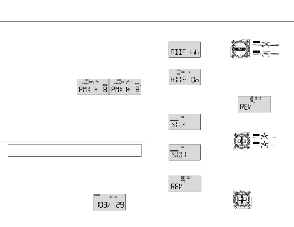
5. Press both Edit keys to get to the regular programming
menu. The end-point adjust menu (EPA) should appear.
Press the Down arrow to get to the aileron differential menu
(ADIF). The display should show that it is inhibited (INH).
6. Turn on the ADIF function by pressing the Clear button until
"On" appears in the display.
7. Be sure that you connect the right aileron servo to receiver
CH1 and the left aileron servo to receiver CH5.
8. You may wish to have the electric motor controlled by an
ON-OFF switch instead of the throttle stick (good for racers
and aircraft that only use full throttle). In this case, go to the
STCK INPUT SELECT menu by pressing the UP or DOWN
arrow key.
9. You can select Switch SW-01 ("ELEV RUDD D/R" to
operate the electronic speed control by pressing the CLEAR
button.
10. Now we will check that each servo moves the proper
direction. If not, we'll use the Reversing function. Go to
the Reversing menu (REV) by hitting the Down arrow.
the left should move downward. Check that the right
aileron moves the correct way! (More planes are crashed
due to reversed controls than for any other reason.)
12. If it does not, activate the opposite direction for the CH1
aileron servo by pressing the Active/Inhibit (Clear) key.
Each press switches from Reversed to Normal and from
Normal to Reversed. In the display, N for Normal is chosen
when the little triangle is above the channel number, and R
for Reversed is chosen when the little triangle is below the
channel number. Move the right-hand stick again and
verify the right aileron moves the right directions. The
display shows Channel 1 reversed.
13. Next we'll set the direction of the elevator servo, channel 2.
When you move the right-hand stick towards the BOTTOM
of the transmitter, the elevator should move up. Check to
make sure it moves the proper direction!
14. If the elevator control moves the wrong direction, move over
to Channel 2 by pressing the Cursor Right key. Now the '2'
should be flashing in the display. Activate the opposite
direction for the elevator servo by pressing the Active/
Inhibit (Clear) key. Move the right-hand stick up-and-down
again and verify the elevator moves the right direction.
15. Now we'll set the direction of the electronic speed control.
If you're using the left-hand stick for throttle control, when
you move the stick towards the TOP of the transmitter, the
motor should spin. It should stop at low throttle stick.
The aircraft setup procedure presented below uses an electric model as an example and assumes that there are two aileron
servos, one in each wing. It also assumes that you are using a micro five-channel receiver. It will take you step-by-step
through the setup process for an electric airplane in the ACGL menu, including the setup for airbrakes.
You can use the other mixer to handle adding aileron
corrections during knife-edge. In this case, you'll have the
same percentage sign on both sides of the rudder.
This introduction just scratches the surface of the
capabilities of your Optic system. Please read the manual
so you'll know what other features you can take advantage
of. The sky's the limit - we know you'll enjoy using your
Optic system!
up elevator for rudder going both directions. Move the
rudder stick to the right and press the Data +Increase until
you can see which way the elevator moves; if incorrect,
press the Data -Decrease key until the plus sign changes
to a minus sign. Repeat this by moving the rudder stick to
the other side. You'll end up with a plus sign for one rudder
direction, and minus for the other direction. Start with only
5-10% mixing on both sides until you know how much you
need from actual test flying.
71. Be sure you understand how to set the switch to turn PMX1
on and off, since you won't want this mixing on during
normal flight, only during knife-edge. Later, after you fly the
model you may fine-tune the amount of elevator travel so
that the pitching tendency is eliminated.
FIVE-CHANNEL ELECTRIC AIRCRAFT SETUP INSTRUCTIONS
LEFT
RIGHT
RIGHT
LEFT
Front View
DOWN
UP
DOWN
UP
HIGH Throttle
LOW Throttle
HIGH
LOW
11. We'll start by setting the right aileron servo direction. This
is channel 1, and the 1 should be flashing for this command.
When you move the right-hand stick to the right, the aileron
on the right wing should move upwards, and the aileron on
Simple Transmitter Setup - Electric Airplane, 5-Channel Receiver (ACGL Menu) - Page 23
Simple Transmitter Setup - Aerobatic Airplane (ACGL Menu) - Page 22
INPUT SEL
INPUT SEL
Flashing "1"
Flashing "1"