Glossary, Helicopter flight trimming chart – HITEC Optic 6 User Manual
Page 29
GLOSSARY
GLOSSARY - Page 57
Helicopter Flight Trimming Chart - Page 56
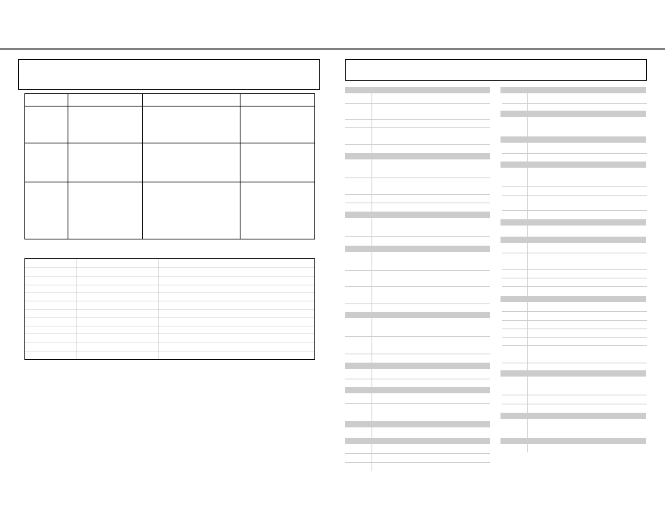
Helicopter Flight Trimming Chart
RPM
Stick
Primary Corrective Action
High
Below 1/2
Decrease hovering throttle
Low
Below 1/2
Decrease hovering pitch
Perfect
Below 1/2
Decrease hovering throttle, decrease hovering pitch
High
1/2 stick
Increase hovering pitch, decrease hovering throttle
Low
1/2 stick
Decrease hovering pitch, increase hovering throttle
Perfect
1/2 stick
Don't touch a thing!
High
Above 1/2
Increase hovering pitch
Low
Above 1/2
Increase hovering throttle
Perfect
Above 1/2
Increase hovering pitch, increase hovering throttle
Want more
Keep 1/2
Decrease hovering pitch, then increase hovering throttle
Want less
Keep 1/2
Increase hovering pitch, then decrease hovering throttle
Adjusting Hovering Pitch and Hovering Throttle
This procedure assumes helicopter is trimmed for hovering. Trimming must be done in near-calm conditions.
Repeat tests several times before making adjustments. If any changes are made,
go back over the previous steps and verify, or further adjust as necessary.
The abbreviations used with the Optic are defined below alphabetically.
Related pages are given in parenthesis following the definition.
A
ACGL
Acrobatic/Glider aircraft menu (15)
ADIF
Aileron differential. Ailerons move more to one
side than other (31)
AILV
Differential elevator servos, for 3-D aerobatics (39)
ATL
Adjustable Travel Limit. Limits throttle trims to
only the throttle idle position.
(built in to your system)
A->R
Aileron Rudder mixing (36)
C
CAMB
A function which droops or raises the entire
trailing edge of a wing. (32)
COPY
Data copy: command used to copy one memory
to another (11)
CROW
Airbrake function (37)
CURSOR Button used to step through menus (9)
D
D/R
Dual rate: switch-controlled function reduces
control travels. (27)
DATA
Editing keys change numbers (9)
E
ELVN
Elevon function combines ailerons & elevators for
tailless models. (34)
EPA
End Point Adjust. Function that adjusts the servo t
ravel at the left and right sides. (27)
EXP
Exponential function, reduces sensitivity around
neutral (28)
E->F
Elevator Flap mixing (36)
F
FAIL
Failsafe function moves servos to preset locations
if interference is received. (41)
FLPN
Flaperon function gives the ailerons a flap
function. (30)
FLPT
Flap travel function. (30)
G
Gear
Landing gear control switch. (8)
GYRO
Gyro setting menu (51)
H
HELI
Helicopter settings menu. (45)
HOLD
Throttle hold function holds the throttle in a near-
idle position (used for autorotation). (51)
I
INH
Inhibit. Function will not operate
L
L/U
Indicates Left or Up stick motion
LAND
Landing function (33)
Lock
Lock throttle button (9)
M
MAS
Master channel in mixer (38)
M.SEL
Model select menu (11)
N
NOR
Normal helicopter swashplate (1 servo each for
elevator, aileron, pitch. (12)
O
OFF
Function or Switch in OFF position.
ON
Function or Switch in ON position.
P
PPM
Pulse-Position Modulation,
also known as "FM". (14)
PCM
Pulse-Code Modulation. (14)
PMX
Programmable mixer. Mixing between
arbitrary channels. (38)
PTCV
Pitch curve function (53)
Q
QPCM
Pulse-Code Modulation. (14)
R
R/D
Indicates Right or Down stick motion
REV
Reverse. Servo operating direction
switching function. (29)
REST
Reset model memory (15)
RVMX
Revolution mixing (54)
R->T
Rudder Throttle mixing (50)
S
S/W SEL
Select on-off switches for different functions (39,53)
SFT.N
Negative transmit shift direction (13)
SFT.P
Positive transmit shift direction (13)
SLV
Slave channel in program mixer (38)
STCK
Choose Mode of transmitter. (13)
STRM
Subtrim function used to adjust
servo neutrals. (28)
SWAH
Swash type (12,54)
T
T.CUT
Throttle cut function used to kill engine
without moving trims (29)
THCV
Throttle curve function (52)
TIME
Timer/Stopwatch function (14)
V
VTAL
V-tail function combines the
elevators and rudder. (35)
Numerical
120'
Helicopter swashplate, 120° (12,54)
To test for...
Test Procedure
Observations
Adjustments
1. RVMX mixing
- Up settings
(Part 1)
Fly the model straight and
level into the wind at 100 ft
altitude, lower pitch to 0°
Observe rotation as helicopter descends
A. No rotation
B. Model rotates counterclockwise
C. Model rotates clockwise
A. None
B. Add right rudder trim
C. Add left rudder trim
2. RVMX mixing
- Up settings
(Part 2)
Bring the helicopter into hover,
add full pitch and ascend 75 ft
Observe rotation as helicopter ascends
A. No rotation
B. Model rotates counterclockwise
C. Model rotates clockwise
A. None
B. Increase UP RVMX mix
C. Decrease UP RVMX mix
3. RVMX Down
mixing settings
Begin Down RVMX mixing
with same number as UP
mix. From inverted flight
(top of loop, or mid-point of
roll, or inverted part of split-S),
add full negative pitch
Observe rotation as helicopter ascends
A. No rotation
B. Model rotates clockwise
C. Model rotates counterclockwise
A. No adjustment
B. Increase Down RVMX mix
C. Decrease Down RVMX mix