HITEC Optic 6 User Manual
Page 3
Airplane Frequencies
Radio Installation Notes
Flying Safety
To ensure your own safety and the safety of others, please
observe the following precautions:
Charge the Batteries!
Be sure to recharge the batteries before each flying session.
A battery low in charge will soon die, causing loss of control
and a crash. Plug in the charger that comes in this system
and hook up the transmitter and airborne batteries the day
before a planned flying session. Be sure the charger is not
turned off by the room's light on-off switch!
When you begin your flying session, reset the transmitter's
timer to keep track of how long the system's been used, and
monitor the transmitter's voltage display. Quit flying when your
transmitter battery level reaches 9.4 volts.
Be careful when you use a field charger on your batteries.
A fast-charger may overcharge the batteries, causing
overheating and a premature failure. Never charge your
transmitter or receiver battery at a rate higher than 2 amps.
Flying field
We recommend that you fly at a recognized model airplane
flying field. You can find model clubs and fields by asking the
nearest hobby dealer, or contacting the Academy of Model
Aeronautics. Always pay particular attention to the flying
field's rules, as well as the presence and location of spectators,
the wind direction, and any obstacles on the field. Be very
careful flying in areas near power lines, tall buildings, or
communication facilities as there may be radio interference in
their vicinity. If you must fly at a site that is not a club field, be
sure there are no other modelers flying within a two-mile range,
or you may lose control of your aircraft.
Once you arrive at the flying field...
Before flying, be sure that the frequency you intend to fly with
is not in use, and secure any frequency control device (pin, tag,
etc.) for that frequency before turning on your transmitter.
Never believe that it's possible to fly two or more models on the
same frequency at the same time. Even though there are
different types of modulation (AM, PPM or FM, and PCM), only
one model may be flown on a single frequency.
When you are ready to fly your model, position the throttle stick
or switch to its low speed position, or do whatever is necessary
to command your motor NOT to run. Then, you may turn on
the transmitter power followed by the receiver power. Use the
LOCK function to prevent accidental throttle commands. When
you have finished flying, begin by turning off the receiver power,
then turn off the transmitter power. If you do not follow these
procedures, you may damage your servos or control surfaces,
flood your motor, or in the case of electric-powered models, the
motor may unexpectedly turn on and cause a severe injury.
Before starting the engine, fully retract the transmitter antenna,
power up the transmitter and receiver, and check to be sure
that the servos follow the movement of the sticks. If a servo
operates abnormally, don't attempt to fly until you determine
the cause of the problem. Finally, before starting the engine,
be sure to check that the transmitter model memory is
correct for the chosen model.While you're getting ready to fly,
if you place your transmitter on the ground, be sure that the
wind won't tip it over. If it is knocked over, the throttle stick
may accidentally get moved causing the engine to race
unexpectedly, causing damage or injury to anyone nearby.
Before taxiing, be sure to extend the transmitter antenna to its
full length. A collapsed antenna will reduce your flying range
and may cause a loss of control. It is a good idea to avoid
pointing the transmitter antenna directly at the model at all
times, since the signal is weakest in that direction.
Finally, don't fly in the rain! Water or moisture may enter the
transmitter through the antenna or stick openings and cause
erratic operation or loss of control. If you must fly in wet
weather during a contest, be sure to protect your transmitter
with a plastic bag or waterproof barrier.
The following frequencies and channel numbers may be used
for flying aircraft in the U.S. (this information specific to North
American versions of the Optic):
While you are installing the battery, receiver, and servos into
your model's fuselage, please pay attention to the following
guidelines:
Mounting
When you mount each servo, use the supplied rubber
grommets and insert an eyelet up through the bottom. Be sure
not to over tighten the screws. If any portion of the servo case
directly contacts the fuselage or the servo rails, the rubber
grommets will not be able to attenuate vibration, which can
lead to mechanical wear and servo failure.
Servo Throw
Once you have installed the servos, operate each one over its
full travel and check that the pushrod and output arms do not
bind or collide with each other, even at extreme trim settings.
Check to see that each control linkage does not require undue
force to move (if you hear a servo buzzing when there is no
transmitter control motion, most likely there is too much friction
in the control or pushrod). Even though the servo will tolerate
loads like this, they will drain the battery pack much more rapidly.
Switch Harness Installation
When you are ready to install the switch harness, remove the
switch cover and use it as a template to cut screw holes and a
rectangular hole slightly larger than the full stroke of the switch.
Choose a switch location on the opposite side of the fuselage
from the engine exhaust, and choose a location where it can't
be inadvertently turned on or off during handling or storage.
Install the switch so that it moves without restriction and "snaps"
from ON to OFF and vice versa.
DO NOT cut or coil the receiver antenna wire. It is normal for
the receiver antenna to be longer than the fuselage. DO NOT
cut it or fold it back on itself - cutting or folding changes the
electrical length of the antenna and may reduce range.
Secure the antenna to the top of the vertical fin or the tail boom,
and let the excess length trail behind the aircraft (be sure it
cannot tangle with the tail rotor on a helicopter).
You may run the antenna inside of a non-metallic housing
within the fuselage (a plastic outer pushrod housing works well
for this), but range may suffer if the antenna is located near
metal pushrods or cables. Be sure to perform a range check
before flying. With the antenna collapsed, you should be able
to walk 20 - 30 paces from the model without losing control or
seeing "jitter" in the servos. The range check should be done
with the motor running and the model should be securely
restrained in case of loss of control.
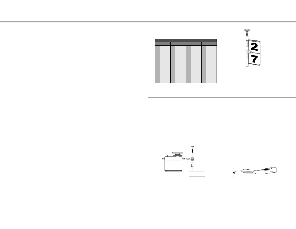
It is very important to display your transmitters channel number
at all times. To install your frequency flag device on your
transmitters antenna, slide the appropriate paper numbers into
the slots and slip the device onto the transmitters antenna.
11
72.010
12
72.030
13
72.050
14
72.070
15
72.090
16
72.110
17
72.130
18
72.150
19
72.170
20
72.190
21
72.210
22
72.230
23
72.250
24
72.270
25
72.290
26
72.310
27
72.330
28
72.350
29
72.370
30
72.390
31
72.410
32
72.430
33
72.450
34
72.470
35
72.490
36
72.510
37
72.530
38
72.550
39
72.570
40
72.590
41
72.610
42
72.630
43
72.650
44
72.670
45
72.690
46
72.710
47
72.730
48
72.750
49
72.770
50
72.790
51
72.810
52
72.830
53
72.850
54
72.870
55
72.890
56
72.910
57
72.930
58
72.950
59
72.970
60
72.990
Ch.No.
MHz
Ch.No.
MHz
Ch.No.
MHz
Ch.No.
MHz
72 MHz band
Notes on Servos
Receiver Notes
Airplane Frequencies, Radio Installation Notes - Page 5
Flying Safety - Page 4