28 gauge conversion instructions – Dillon Precision SL 900 User Manual
Page 36
A 28 gauge conversion package (#22139),
includes the following items:
1.) A complete toolhead assembly with dies
installed; Station 1, collet sizer & depriming pin
assembly. Station 2, powder die with 28 gauge
powder funnel and retaining clip. Station 3, complete
shot dispenser assembly with 1/2 oz – 1.0 oz shot bar
and 28 gauge shot drop tube. Station 4, starter crimp
star/radius form insert. Station 5, new spring/over
floating taper crimp die.
2.) A 28 gauge conversion kit box containing: (a)
one 28 gauge shellplate (#10625), (b) three locator
buttons (#16753) with locator rings (#10602) and
springs (#17126), (c) one green station 2 locator
insert (#10624), (d) two green wad guides (1 spare,
#10620), (e) one 28 gauge casefeed sleeve assembly
(#22129). Fig. 1
Converting the Machine
The following is a step by step routine to use for
converting your machine to reload other gauges.
Refer to your SL 900 reloading manual as needed.
1. Drain the shot via the shot dispenser drain.
Hint, use an old coffee can, widemouth water jug or
shot bag to catch the shot.
2. Disconnect the return rods on both the shot and
powder dispensers.
3. Remove the shot fitting e-clip on the shot
dispenser and slide the fitting out of the dispenser
housing.
4. Remove the two black toolhead pins and
remove the toolhead from the machine.
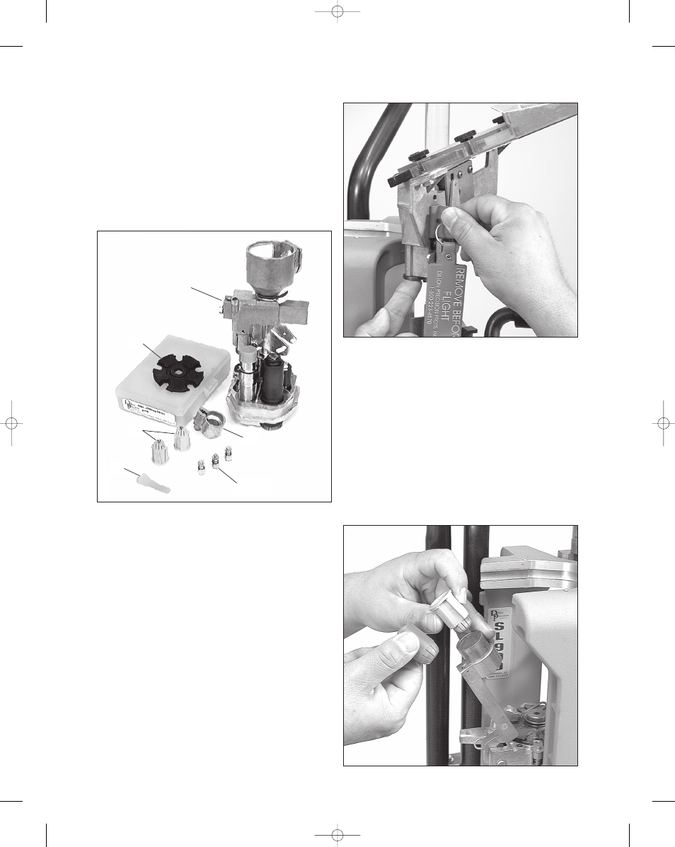
5. Install the red flag block into the primer feed
assembly.
Fig. 2
Replacing the Shellplate and
Parts in the Platform
1. Remove the ejector wire (#16676).
2. Move the roller handle to the down position.
3. Use a 1/8" Allen wrench to loosen the 1/4-28
brass tip set screw 1/2 a turn. The brass tip set screw is
located on the left side of the machine, below the
platform, in the mainshaft.
4. While the machine is in this configuration, it is
a good time to exchange the red wad guide (12
gauge) with the green wad guide (28 gauge). Fig. 3
28 Gauge Conversion Instructions
Fig. 1
Fig. 3
Fig. 2
a
toolhead
assembly
b (3)
c
d
e
36
SL 900, May 2007 5/21/07 11:51 AM Page 36