Step by step preliminary assembly – Dillon Precision SL 900 User Manual
Page 17
The automatic primer system holds 100 shotshell
primers. Every complete stroke of the roller handle
(#22183) will feed a primer to the hull.
The automatic powder system is also located at
station two. The hopper holds one half pound of
powder and has a fully adjustable powder bar. The
automatic powder system is hull activated. Move the
roller handle (#22183) down. When the hull contacts
the expander/powder funnel (#16746), the powder
measure is pushed up, causing the powder bar to
move and dispense one charge of powder into the
hull. Raise the roller handle (#22183) to its rest
position. The powder bar will recharge and the hull
will advance to station three.
At the third station (left, front of the machine) we
will insert the wad and meter the shot into the shell.
Move the roller handle (#22183) aft as if you are
seating a primer into the hull. You will see the wad
swing arm (#16677) tilt out, ready to accept a new
wad. With every complete stroke of the roller handle
(#22183), insert a new wad into the wad swing arm
(#16677) when it tilts out.
Move the roller handle (#22183) down. The shot
drop tube (#16726) inserts the new wad into the
empty hull and will dispense shot into the hull. Raise
the roller handle (#22183) and push aft to prime.
Hold the handle aft while you insert a wad into the
swing arm.
At station four we start the crimp in the top of the
loaded hull. It is formed and folded closed, preparing
the hull for the final crimp and seating performed in
station five.
The formed, folded top of the hull will now be
crimped and seated closed. This die is fully
adjustable. The crimp and seating depth can be
adjusted to the desired settings.
This die also has a taper crimp feature inside that
will form a tapered end to the hull. Again, move the
roller handle (#22183) down and then back up to its
rest position. The completed shotshell advances out of
the machine, down the shotshell chute (#16672) and
into the Dillon bin (#17125).
Step by Step Preliminary Assembly
1. Fasten the strong mounts (#16065) to the base
of the machine while it is lying on its side. Fig. 2
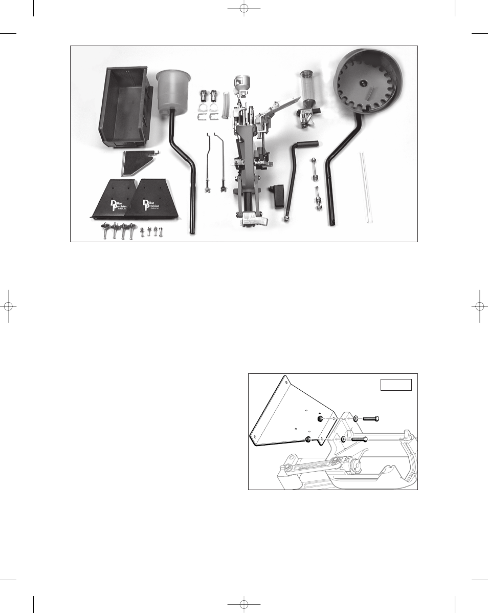
Fig. 1 - A.) Dillon Bin B.) Shotshell Chute C.) Strong Mounts D.)
Universal Mounting Kit and Hardware needed for Strong Mount
installation E.) Shot Container and Post F.) Shot Dispenser Hardware
G.) Shot Bar Return Rod and Powder Bar Return Rod
H.) SL 900 Toolhead and Frame I.) Spent Primer Cup J.) powder
measure K.) Roller Handle L.) Hardware for Shot Post and Casefeed
Post Assembly M.) Casefeed Bowl and Post N.) Clear Casefeed Tube
A.
B.
C.
D.
E.
F.
G.
H.
I.
J.
K.
L.
M.
N.
Fig. 2
17
SL 900, May 2007 5/21/07 11:51 AM Page 17