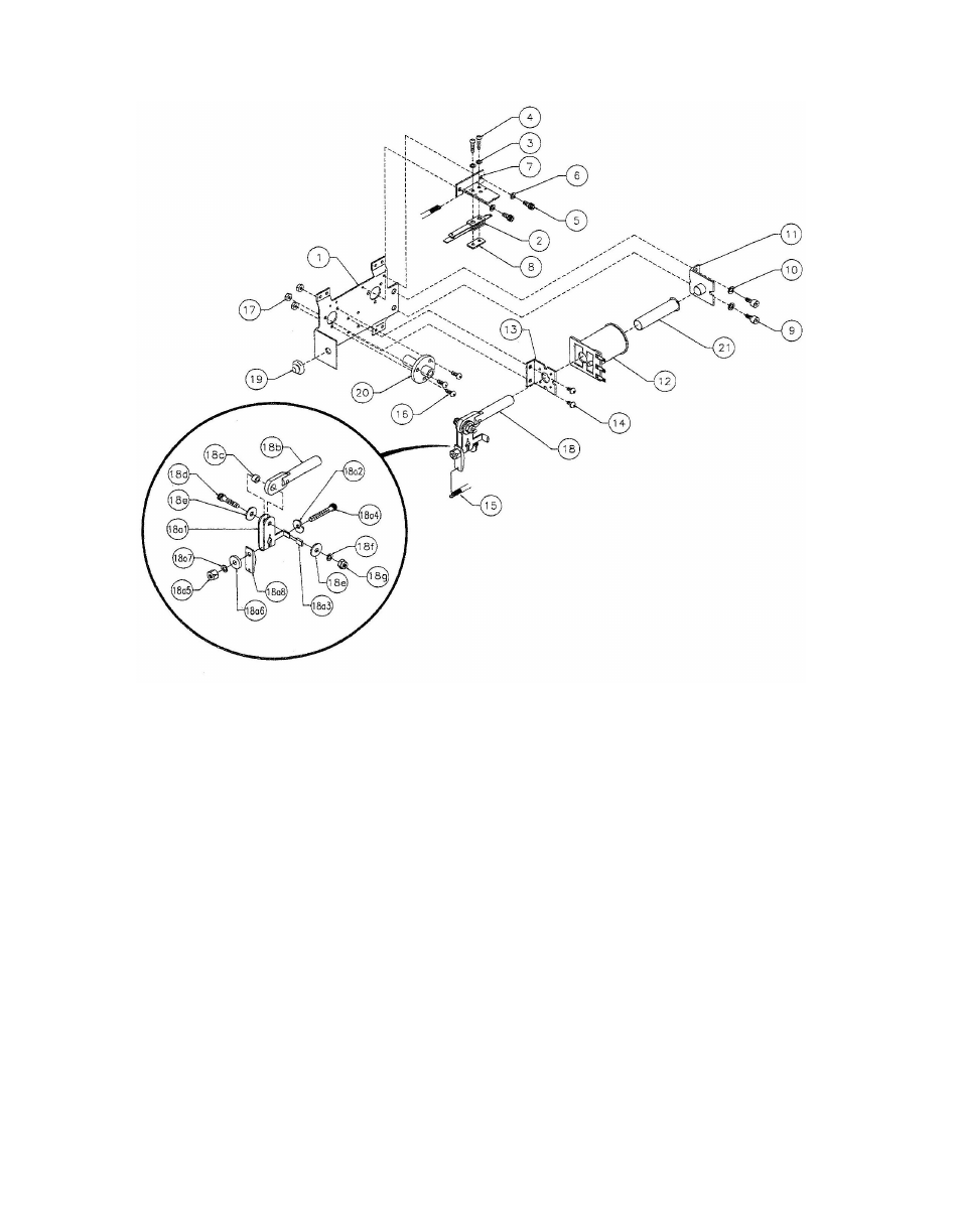
Chicago Gaming Medieval Madness Remake User Manual
Page 93
Item
Part Number
Description
18
A-15848-R
Crank Link Assembly, Right
a)
A-17050-R
Flipper Crank, Right
2.
4700-00107-01
Mod Crank Washer
3.
RM-23-06
Item
Part Number
Description
4.
4010-01066-20
Nut, 10-32 Hex.
1
B-13104-R
Flipper Base Assembly, Right.
6.
4700-00107-00
FW, 13/64 x 5/8 x 12ga.
2
SW-1A-194
Switch Assembly
7.
4701-00004-00
Lockwasher #10 Split
4
4105-01019-10
Sh. Metal Screw, #5 x 5/8"
b)
A-15847
Flipper Link Assembly
5
4008-01079-05
Mach. Screw, 8-32 x 5/16"
c)
02-4676
Link Spacer Bushing
6
4701-00003-00
Lock Washer #8 Split
d)
4010-01086-14
Cap Screw, 10-32 x 7/8"
7
01-9375
Switch Mounting Bracket
e)
4700-00023-00
Flat Washer, 5/8 x 13/64 x 16ga.
8
20-6516
Speednut, Tinnerman
f)
4701-00004-00
Lock Washer #10 Split
9
4010-01066-06
Cap Screw, 10-32 x 3/8"
g)
4410-01132-00
Nut 10-32 ESN
10
4701-00004-00
Lock Washer #10 Split
19
23-6577
Bumper Plug, 5/8"
11
A-12390
Flipper Stop Assembly
20
03-7568
Flipper Bushing
12
FL-11629
Flipper Coil, Blue
21
03-7066-5
Coil Tubing
13
01-7695-1
Solenoid Bracket
14
4006-01017 -04
Mach. Screw, 6-32 x 1/4"
Associated Parts:
15
10-364
Spring
23-6695
Flipper Ring
20-10110-5
Flipper Bat w/Shaft
PIN-A-15849R2
Flipper Assembly
RE
F
.
3
4701-00002-00
Lock Washer #6 Split
8.
01-9376
Spring Retainer Bracket
Flipper Crank Assembly, Right
1.
01-11764-R
(Not Shown)
16
FSM-063-PPH043C Mach. Screw, 6-32 x 7/16"
17
FNT-063-ESNA125 Nut 6-32 Nylock, 1/8" Tall
Flipper
Notes
:
1. Each Flipper Assembly is mounted beneath the playfield, in conjunction with the Plastic Flipper & Shaft, and Flipper Rubber on the upper side of the playfield,
2
. With the flipper, in the non-activated position, the E.O.S. Switch contacts must have
a
gap of .062 (±.015) inch. When flipper is activated switch must close.
3. Any adjustment of the E.O.S. switch must be made at
a
minimum distance of 0.25 inch from the switch body.
4
.
Longer blade of E.O.S, switch must be made straight. Gap adjustment is done by adjusting shorter blade.
5
. All moving elements of the assembly must operate freely without any evidence of binding.
6
. Apply Loctite
290 when reattaching screws to the Flipper Stop Assembly and the Solenoid Bracket
H.S. Tubing,
1/4"
MS, 10-32 x 1-
1/4"
5.
4410-01127-00
2-10