12 jumper settings, Load bios default jumper (jp1), Xmc vpwr select jumper on db-3umc (jpx1) – ADLINK cPCI-3970 Series User Manual
Page 80: Pmc v(i/o) select jumper on db-3umc (jpx2)
66
Board Interfaces
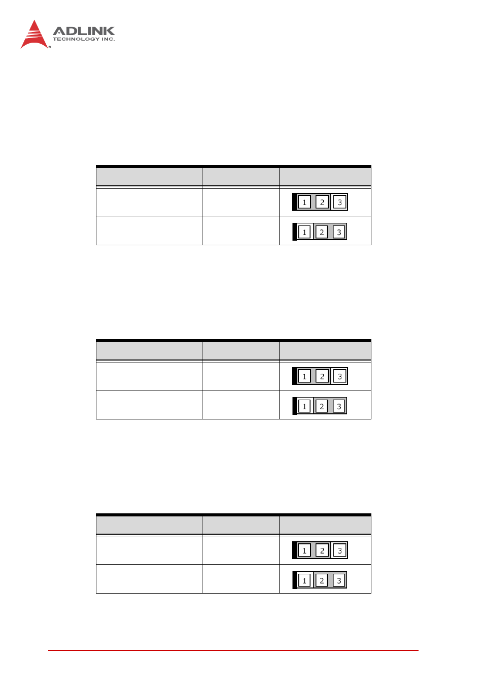
4.12 Jumper Settings
Load BIOS Default Jumper (JP1)
The cPCI-3970 Load BIOS Default Jumper is located on the
DB-3CF/CFast daughter board. To load the default BIOS settings,
short pins 2-3 on JP1, then reinstall the jumper cap to pins 1-2.
Table 4-33: Load BIOS Default Jumper Settings
XMC VPWR Select Jumper on DB-3UMC (JPX1)
This jumper is located on the DB-3UMC board near JN1/2 and
selects the XMC VPWR setting. 5V is set by default.
Table 4-34: XMC VPWR Select Jumper Settings
PMC V(I/O) Select Jumper on DB-3UMC (JPX2)
This jumper is located on the DB-3UMC board near JN1/2 and
selects the PMC V(I/O) setting. 3.3V is set by default.
Table 4-35: PMC V(I/O) Select Jumper Settings
BIOS Setting
Connection
JP1
Normal
1 – 2
Load default BIOS
2 – 3
Mode
Connection
JPX1
+5V (Default)
1 – 2
+12V
2 – 3
Mode
Connection
JPX2
+5V
1 – 2
+3.3V (Default)
2 – 3
This page intentionally left blank.