Delta N028314 User Manual
Page 18
18
The saw table was aligned at the factory so that the miter gauge slots are parallel to the saw blade. However, check the
alignment before initial operation.
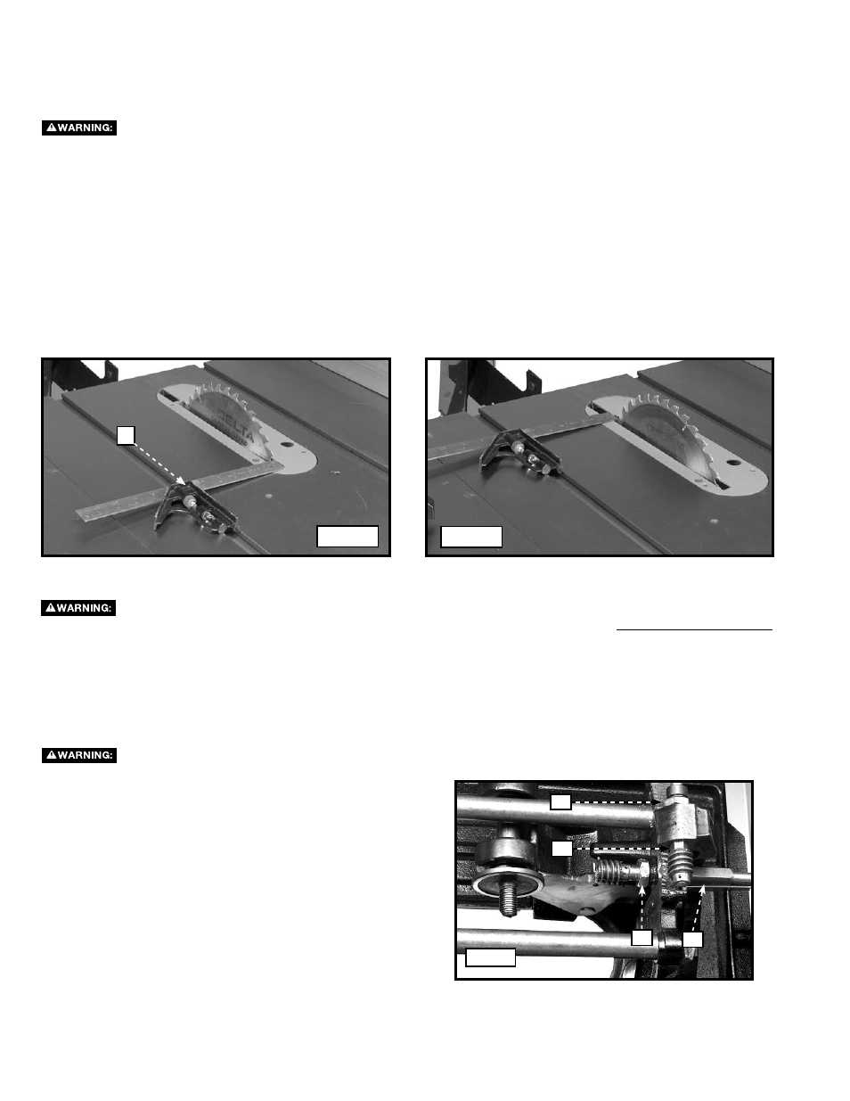
ALIgNINg THE BLAdE TO THE MITER SLOTS
A
Fig. 39
Fig. 40
disconnect the machine from the power source.
AdJUSTINg BLAdE ALIgNMENT
Blade Alignment is factory-set and should not need adjustment. Aligning the blade in the field is a
difficult and time-consuming procedure. For assistance with your machine, check the web site www.deltaportercable.com
or call the DELTA Machinery help line at 1-800-223-7278 (In Canada call 1-800-463-3582).
1. Place a combination square (A) Fig. 39 on the table with one edge of the square in the miter gauge slot. Adjust the square
so that the ruler touches one of the teeth on the saw blade at the forward position (Fig. 39). Lock the square in this
position.
2. Rotate the saw blade so that the same tooth used in
STEP 1 is in the rear position (Fig. 40). Check this distance. Both the
front and rear measure ments should be identical.
3. To adjust, loosen the two hex head bolts (T) Fig. 15 that hold the rear trunnion to the saw table.
4. Use a rubber mallet (or a regular hammer and a block of wood) to tap the trunnion until the saw blade is in the center of
the throat plate slot, and parallel to the miter gauge slot.
5. Tighten the two hex head bolts that were loosened in
STEP 3.
6. Tilt the blade to 45
°. Turn the saw blade by hand to ensure that it does not contact the throat plate.
BACKLASH AdJUSTMENTS FOR BLAdE-AdJUSTINg MECHANISMS
If any play is detected in the blade-raising or blade-tilting mechanisms, do the following:
1.
Adjusting the elevation mechanism - Loosen the
locknut (A) Fig. 42 and turn the eccentric sleeve (B) until
all play is removed. Tighten the locknut.
2.
Adjusting the tilting mechanism - Loosen the locknut
(C) Fig. 42 and turn the eccentric (D) until all play is
removed. Tighten the locknut.
disconnect the machine from the power source.
C
d
A
B
Fig. 42