Appliance description, 2 installation, 3 temperature limiting/anti-scalding protection – STIEBEL ELTRON DHB-E 13 SL User Manual
Page 24: F» installation versions, 5 special accessories, 1 standard delivery
Attention! The text in this document has been recognized automatically. To view the original document, you can use the "Original mode".
INSTALLATION
APPLIANCE DESCRIPTION
8. Appliance description
The bare wire heating system is suitable for hard and soft water
areas. The heater has low susceptibility to scale build-up.
The outlet temperature can be infinitely adjusted. The electronic
control unit enables automatic matching of the electrical output
corresponding to the selected temperature subject to the actual
throughput.
8.1 Standard delivery
-Mounting bracket
-Installation template
-Twin nipple
-Cross-piece
-Tee
-Flat packing
-Sieve
-Flow limiter
-Plastic profile washer
-Plastic cap
-Flexible plastic couplings
-Cap and back panel guides
8.2 Installation
The following conditions have been prepared for the appliance
at the factory:
-Power supply from 'below", installation on unfinished walls
-Water connection, installation on unfinished walls
The appliance must be fitted vertically, over or undersink, to a
solid wall.
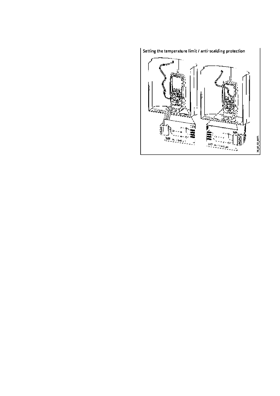
8.3 Temperature limiting/anti-scalding protection
The maximum temperature can be limited to 43 *C via the user
interface on the appliance cap. The following steps are necessary
for this procedure:
» Remove the appliance cap.
»Remove the electronic PCB from the user interface on the
appliance cap. Be careful of the snap-on hooks.
» Move the plug from left to right (position 'A3 *C").
»Refit the user interface, ensuring the snap-on hooks click into
place. Observe the positions of the pushbutton and shaft.
8.f» Installation versions
The following installation versions are possible/permissible:
-Power supply for unfinished walls - from above
-Power supply For finished walls
-Water installation for finished walls
-Installation with repositioned appliance cap
-1 nstal lalion for offset tiles
-Installation of a load shedding relay
8.5 Special accessories
8.5.1
Twiu'lever taps (mains pressure)
- WKMD - Kitchen taps, part num ber 222A37
-WBMD- Bathroom taps, part number 222438
8.5.2
Installation accessories
-Undersink installatTon pipe assembly, part number 070565,
Connections: Finished walls. G 3/8'. above.
-2 pee. G vr water plug set. part number 074326.
These plugs are required for third party pressure valves.
8.5.3
Installation sets for installation on finished walls
- Solder fitting - copper pipe, part nu mber P74019, comprising: 2
X 6 V:" water plugs and 2 x union nuts Vi" with insert for solder
fitting 0 12 mm.
-
Compressionfitfing* copper pipe, part number222380, comprising:
2xG W water plugs and 2 x compression fittings V
2
"x 15 mm,
plus gaskets.
-Compression
fitting
**
plastic
pipe,
part
number
222381,
comprising: 2 x G W water plugs and 2 xcompression fittings Vi"
X16 mm (Viega: Sanfix-Plus. orSanfix-Fosta). plus gaskets.
8.5.4
Universal mounting frame
Part
number
220291.
comprising:
Mounting
frame
with
electric
wiring. This set creates a gap of 30 mm between the back panel
of the appliance and the installation wall. This enables the power
supply
to
be
freely
routed
over
unfinished
walls
behind
the
appliance. This increases the appliance depth by 30 mm. This set
reduces the protection to IP 24 (splashproof).
24 IDHB-E ... SiL electronic
vrww.stiebeL-el.tron.com