V. gas supply, V. gas supply caution, Figure 2-12 - flexible gas hose installation – Blodgett S1820G User Manual
Page 21
Attention! The text in this document has been recognized automatically. To view the original document, you can use the "Original mode".
V. GAS SUPPLY
CAUTION
DURING PRESSURETESTiNGNOTETHEFOLLOWING:
1. The oven and its individual shutoff valve must be discon
nected from the gas supply piping system during any
pressure testing of that system attest pressure in excess
of 1/2 psi (3.45 kPa).
2. The oven must be isolated from the gas supply piping
system by closing its individual manual shutoff valve dur
ing any pressure testing of the gas supply piping system
at test pressure equal to or less than 1/2 psi (3.45 kPa).
3.
If incoming pressure is over 14" W.C. (35mbar), a
separate regulator MUST be installed in the line BEFORE
the Individual shutoff valve for the oven.
WARNlNG:To prevent damage to the control valve regu
lator during initiai turn- on of gaSj it is very Important to
open the manual shutoffvalve very slowly.
After the initial gas tum-on, the manual shutoff valve must
remain open except during pressure testing as outlined in the
above steps or when necessary during service maintenance.
A Gas Utility Rough-ln Recommendations
The following gas system specifications are STRONGLY
RECOMMENDED.
Deviating
from
these
recommendations
may affect the baking performance of the oven.
Gas Meter - 650 cfh (307^/min) meter
Gas Line
•
DEDICATED LINE from the gas meter to the oven
•
1-1/2" (50.8mm) pipe for natural gas
•
1-1/2" (38.1mm) pipe for propane
•
Maximum length: 200'(61m). Each 90“ elbow equals 7'
(2.13m) of pipe,
B. Gas Conversion
Where permitted by local and national codes, it is possible to
convert ovens from natural to propane gas, or from propane to
natural gas. Use the appropriate Middleby Gas Conversion Kit
for the specific oven model.
CAUTION:
The terms of the oven’s warranty require all start
ups, conversions and service work to be per
formed by a Middleby Authorized Service Agent
C. PS536 Propane Conversion
Two items have to be changed, to change the oven to LP;
1.
Replace main orifices.
2.
Adjust main gas regulator per instructions below.
Disconnect the manifold union closest to the main burner, and
remove the manifold assembly (four screws). Slide out the
manifold assembly (leaving the ignition and sense wires con
nected). Replace the main orifices.
Repiace the main orifices on the manifold assemblies with the LP
units, and repiace the manifoid assembly. Reconnect the union.
D. Adjusting the Maximum Pressure Setting
1. Disconnect pressure feedback connection (if appcable).
2.
Connect a suitable pressure gauge to pipe line or to
outlet pressure tap of gas control concerned, to mea
sure burner pressure (measuring point must be as
near to burner as possible).
3.
Make sure that the appliance is in operation and the
Moduplus® coil is energized with maximum current.
4.
if maximum rate pressure needs adjustment, use an 8
mm wrench to turn adjustment screw for maximum pres
sure setting (ciockwise to increase or counter-clockwise
to decrease pressure), until the desired maximum outlet
pressure is obtained.
5.
Disconnect electrical connection of the Moduplus®.
6.
Check minimum pressure setting and readjust if neces
sary. (See Adjusting Minimum Pressure Setting for
proper adjusting procedure.)
7.
Reconnect pressure feedback connection (if appcable).
8.
if minimum and maximum pressures are set, wire the
Moduplus® in circuit.
9.
Close pressure tap screw.
E Adjusting the Minimum Pressure Setting
1.
Disconnect pressure feedback connection (if appcable).
2.
Connect a suitable pressure gauge to pipe tine or to outlet
pressure tap of gas control concerned, to measure burner
pressure (measuring point must be as near to burner as
possible).
Disconnect electrical connection of the Modupius®,
Energize operator, set control in operation and wait until
an outlet pressure is recorded on pressure gauge.
5. if minimum rate pressure needs adjustment, use an 8
mm wrench to turn adjustment screw for minimum
pressure setting (clockwise to increase or counter
clockwise to decrease pressure), until the desired mini
mum outlet pressure is obtained.
Check if main burner lights easily and reliable at mini
mum pressure.
Reconnect pressure feedback connection (if appcable).
Close pressure tap screw.
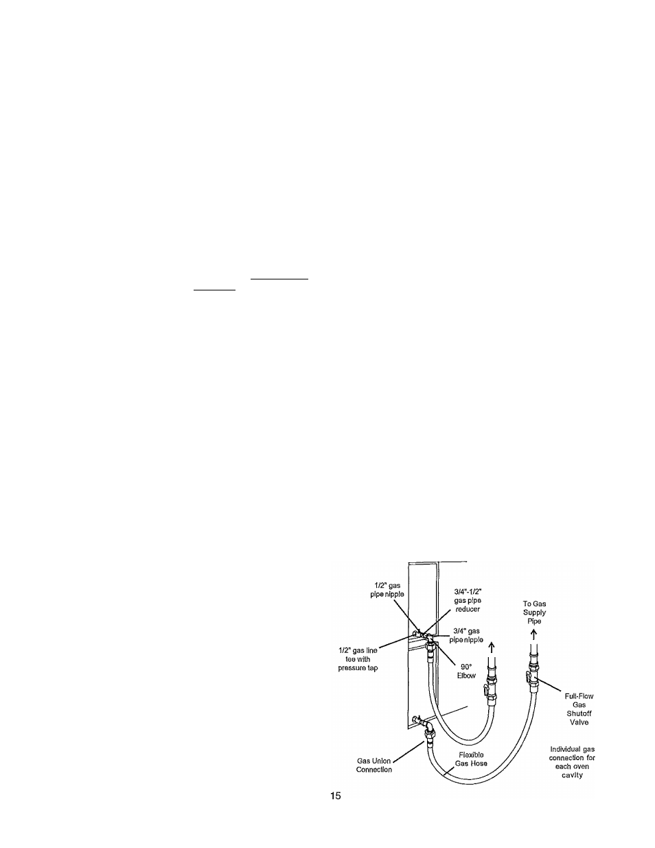
Figure 2-12 - Flexible Gas Hose Installation
SECTION 2
INSTALLATION
3.
4.
6
.
7.
8
.