Ii. component function, B. blower fan, C. gas burner – Blodgett S1820G User Manual
Page 10
Attention! The text in this document has been recognized automatically. To view the original document, you can use the "Original mode".
II. COMPONENT FUNCTION
A. Conveyor Motor and Conveyor Belt
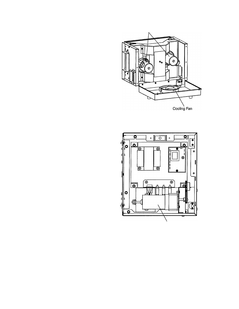
The conveyor belt is driven by a variable-speed electric
motor (Figure 1 -5) operating through a gear reducer. The
motor speed is controlled by a digital control. The stain
less-steel wire belt can travel in either direction at variable
rates ranging from 1 minutes to 10 minutes; this is the time
that a product can take to pass through the oven.
B. Blower Fan
The blower fans are located at the rear of the oven. These
blowers force heated air through the air fingers. The
BLOWER switch must be set to “ON” or “I” for oven
warmup and baking.
C. Gas Burner
The gas burner is located inside the rear panel and is
controlled by the temperature controller.
D. Cooling Fan — See Figure 1-5 and Figure 1-6
The cooling fan is located in the back of the oven. The
cooling fan draws air through its grille, blowing it through
the blower motor compartment and the control compart
ments into the oven top and exhausted out the front
louvers.
E. Air Fingers and Blank Plates - See Figure 1-7
El. Air Fingers
An Air Finger Assembly is made up of three parts:
1
. Outer Plate
- The Outer Plate is the removable covering
with tapered holes, which direct the air stream onto the
product being baked.
2.
Inner Plate
-The perforated inner Plate is vital informing
the unique air jets, it must be assembled Into the manifold
with its holes aligned with the holes of the outer plate.
3.
Manifold
- The Manifold is the assembly which slides
on tracks into the oven plenum.
SECTION 1
DESCRiPTlON
Blower Motor
Blower Assembly
Conveyor Drive Motor
Left Control Box
Figure 1-5. Machinery Compartment
Components