A caution – Carrier 38E User Manual
Page 9
Attention! The text in this document has been recognized automatically. To view the original document, you can use the "Original mode".
every 30, 50 or 90 minutes of operating time. Control
board has additional feature that allows unit to restart in
defrost cycle if room thermostat is satisfied during
defrost.
Troubleshooting defrost control involves a series of
simple steps that indicate whether board is defective.
NOTE: Procedure allows mechanic to check control
board and defrost thermostat for defects. First, trouble
shoot to make sure unit operates properly in heating and
cooling modes. This ensures problems are not attributed
to the defrost control board. Additional steps follow:
1. Turn thermostat to OFF. Disconnect all power to
outdoor unit.
2. Remove control box cover for access to electrical
components and defrost control board.
3. Disconnect defrost thermostat leads from control
board, connect to ohmmeter. Thermostat leads are
the heavy-gage black insulated wires connected to
DFT and C terminals on control board. Resistance
reading may be 0 (indicating closed defrost thermo
stat) or infinity ( oo for open thermostat) depending
on outdoor temperature.
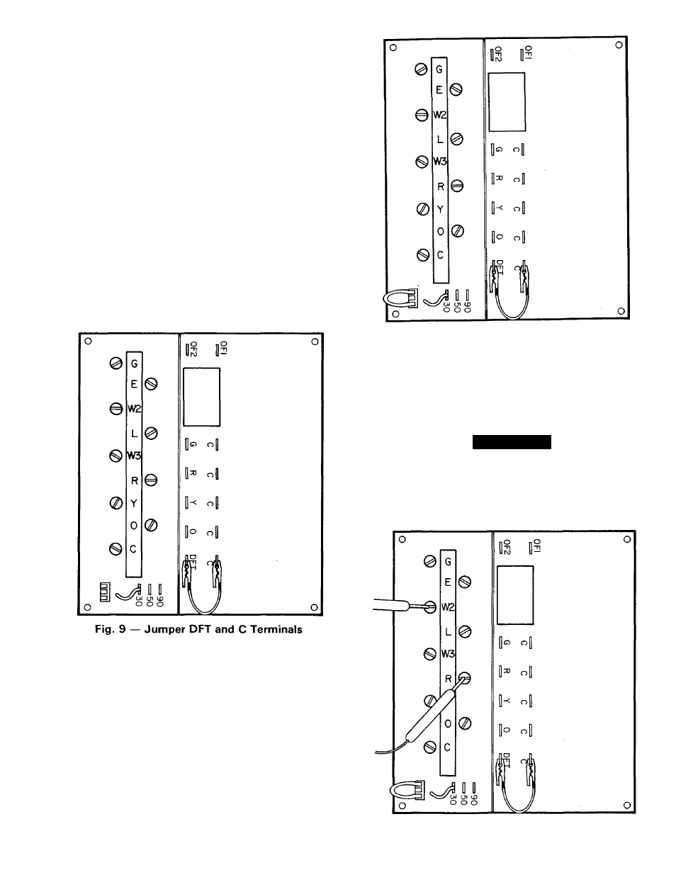
4. Jumper between DFT and C terminals on control
board as shown in Fig. 9.
5. Disconnect outdoor fan motor lead. Tape lead to
prevent grounding.
6. Restart unit in heating, allowing frost to accumulate
on outdoor coil.
7. After a few minutes in heating, liquid line tempera
ture should drop below closing set point of defrost
thermostat. Using ohmmeter, check resistance across
defrost thermostat leads. Resistance of 0 indicates
defrost thermostat is closed and operating properly.
8. Remove protective cover from TPl and TP2 speed
up terminals. Insert jumper wire into protective
cover, reinsert protective cover on speed-up termi
nals. This reduces by 1 / 4 timing sequence of original
time (see Fig. 10). Since Fig. 10 shows timing cycle set
at 30 minutes, unit initiates defrost within approxi
mately 30 seconds; if setting is at 50 minutes, within
Fig. 10 — Inserting Jumper Wire
into Protective Cover
50 seconds; 90 minutes, within 90 seconds. When you
hear reversing valve change position, remove protec
tive cover/jumper, otherwise control will terminate
normal 10-minute defrost cycle in approximately
10 seconds.
A CAUTION
Do not use screwdriver or other means to short
speed-up pins. If pins are accidentally grounded,
control board is destroyed.
9. Unit is now operating in defrost mode. Using volt
meter, check between R and W2 as shown in Fig. 11.
Fig. 11 — Checking Between R and W2