A caution – Carrier 38E User Manual
Page 7
Attention! The text in this document has been recognized automatically. To view the original document, you can use the "Original mode".
220-V FROM UNIT
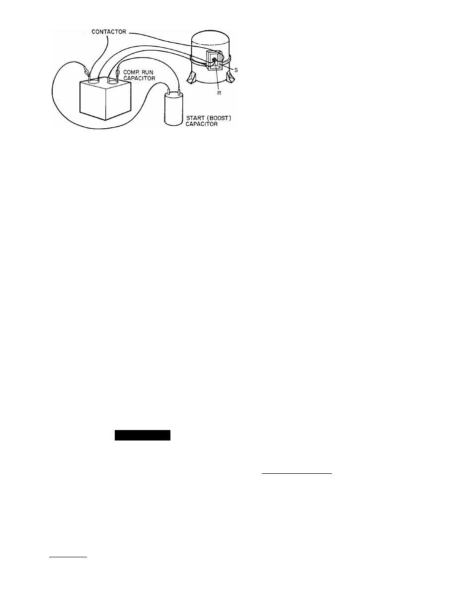
Fig. 7 — Capacitance Boosting
Turn off power. Check compressor for ground or open.
If there is none, proceed. Obtain a start capacitor
approved by compressor manufacturer. Connect wires
with insulated probes to each terminal. Touch probes to
each side of run capacitor. Energize and start compressor,
pull probes away after about 3 seconds. Discharge start
capacitor. Run compressor about 10 minutes. Stop and
allow to sit idle about 5 minutes. Check system pressure
equalization. Attempt to restart without capacitance
boost. If compressor does not start after several attempts,
add proper auxiliary start capacitor and relay.
If PTC thermistor device is inadequate as start device,
a start capacitor and relay may be added to system to
insure positive start. Capacitor is wired in parallel with
run capacitor through normally closed set of contacts on
a device called start relay. The relay coil is wired across
start and common terminals of cornpressor. The added
capacitance gets compressor started. As compressor
comes up to speed, voltage across start and common
terminals increases to a value high enough to cause start
relay to energize. This opens normally closed contacts
and removes start capacitor from circuit. In actual
practice, this occurs in a fraction of a second.
To check start relay and capacitor, first turn off all
power to unit. Discharge start and run capacitors as
outlined earlier. Most start capacitors will have a 15,000-
ohm, 2-watt bleed resistor. Disconnect these devices from
system. Start capacitor can be inspected visually. It is
designed for short duration or intermittent duty. If left in
circuit for prolonged period it blows through a specially
designed orifice. If it appears blown, check for stuck
contacts in start relay. Start capacitor can be checked
by ohmmeter method discussed earlier.
A CAUTION
If bleed resistor is wired across start capacitor, it
must be disconnected to avoid erroneous readings
when ohmmeter is applied across capacitor.
Start relay is checked with ohmmeter. Check for
continuity across coil of relay. You should encounter a
high resistance. Since relay contacts are normally closed,
you should read low resistance across them.
Both PTC device and capacitor relay start system are
standard equipment on some of these units. They are also
available as accessories and may be field installed.
TIME GUARD II — (See Fig. 8.)
Description — Solid-state Time Guard device protects
unit compressor by preventing short cycling. After a
system shutdown. Time Guard provides for a 5 ± 2-
minute delay before compressor restarts. On normal
start-up, 5-minute delay occurs before thermostat closes.
After thermostat closes. Time Guard device provides a
3-second delay to prevent contactor chattering.
Time Guard 11 device is simple to troubleshoot. Only a
voltmeter capable of reading 24 v is needed. Device is
in control circuit, therefore, troubleshooting is safe with
control power (24 v) on and high-voltage power off.
With high-voltage power off, attach voltmeter leads
across T1 and T3, set thermostat so that Y terminal is
energized. Make sure all protective devices in series with
Y terminal are closed. Voltmeter should read 24 v across
T1 and T3. With 24 v still applied, move voltmeter lead
from T1 terminal to T2 terminal. After 5 ± 2 minutes,
voltmeter should read 24 v, indicating control is
functioning normally. If no time delay is encountered,
or device never times out, change control. A schematic
diagram printed on device enables you to troubleshoot
this device.
CRANKCASE HEATER — Crankcase heater is a device
for keeping compressor oil warm. By keeping oil warm,
refrigerant does not migrate to and condense in com
pressor shell. This prevents flooded starts which can
severely damage compressor.
Crankcase heaters come in 2 basic types, wraparound
(belly-band) type that is wrapped externally around
compressor shell, and insertion type that is inserted into
compressor oil well in shell of compressor. Both types
are in this family of units.
Crankcase heater is powered by high-vo\tagt power of
unit. Use extreme caution troubleshooting this device
with power on. Easiest method of troubleshooting is to
apply voltmeter across crankcase heater leads to see if
heater voltage is on. Carefully feel area around crankcase
heater. If warm, crankcase heater is probably function
ing. Do not rely on this method as absolute evidence
heater is functioning. If compressor has been running,
area will still be warm.
With power off, and heater leads disconnected, check
across leads with ohmmeter. Do not look for a specific
resistance reading. Check for resistance or an open
circuit. Change heater if an open circuit is detected.
Some crankcase heaters in this series of units are
equipped with crankcase heater switch installed in series
with heater. This energy-saving device shuts off power to
heater when temperatures are high enough that heater
is not needed. Be sure this switch is functioning normally
before condemning crankcase heater.
PRESSURE SWITCHES — Pressure switches are pro
tective devices wired into control circuit (low voltage).
They shut compressor off if abnormally high or low
pressures are present in refrigeration circuit. Depending
on unit model, you may find a low- or high-pressure
switch, or both, in system.
Low-Pressure Switch — Located on suction line, protects
against low suction pressures caused by such events as
loss of charge, low airflow across indoor coil, dirty
filters, etc. It opens on a pressure drop at about 30 psi.
If system pressure is above this, switch should be closed.
To check switch, turn off all power to unit, disconnect
leads on switch, apply ohmmeter leads across switch.
You should have continuity on a good switch. Because
these switches are attached to refrigeration system under
pressure, it is not advisable to remove this device for
troubleshooting unless you are reasonably certain that a
problem exists. If switch must be removed, bleed all
system charge so that pressure gage reads 0 psi.