A caution – Carrier 38E User Manual
Page 17
Attention! The text in this document has been recognized automatically. To view the original document, you can use the "Original mode".
This type of fitting is easily repaired if leaks develop.
Frontseat outdoor section service valves after relieving
refrigerant pressure in system. Back locknut off Carrier
Compatible Fitting onto tube. Cut fitting between
threads and 0-ring. Remove tubing section remaining
in threaded portion of fitting. Discard locknut.
Clean, flux and insert new tube end into remaining
portion of Carrier Compatible Fitting. Wrap valve in wet
cloth to prevent damaging valve. Heat and apply low-
temperature solder (430 F [221 C]).
Leaking Sweat Connection — Frontseat service valves
and relieve refrigerant pressure in tubing. Clean and
flux area around leak and apply low-temperature
solder (430 F [221 C]).
Liquid line service valves on all heat pump models
differ from condensing unit valves in that heat pump
connection has 3/8-in. male flare. When making connec
tion, remove flare nut, install it on liquid line prior to
flaring. Flare liquid line using standard flaring tech
niques. Valve also contains piston and retainer. Service
as follows:
ACCURATER"“ (Bypass Type) COMPONENTS —
(See Fig. 23.) AccuRater piston has a refrigerant metering
hole through it. Retainer forms a stop for piston in
refrigerant bypass mode, and a sealing surface for liquid
line flare connection. To check, clean or replace piston:
1. Shut off power to unit.
2. Pump unit down using Pumpdown Procedure des
cribed in this Service Manual.
3. Remove liquid line flare connection from AccuRater.
4. Pull retainer out of body, being careful not to scratch
flare sealing surface. If retainer does not pull out
easily, carefully use locking pliers to remove it.
5. Slide piston out by inserting a small soft wire, with
small kinks, through metering hole. Do not damage
metering hole, sealing surface around piston cones or
fluted portion of piston.
6. Clean piston refrigerant metering hole.
7. Replace retainer 0-ring (Part No. 99CC501052)
before reassembling bypass-type AccuRater.
FLARE NUT
Fig. 23 — AccuRater™ (Bypass Type) Components
Service valves provide a convenient shutoff valve useful
for certain refrigeration system repairs. System may be
pumped down to make repairs on low side without losing
complete refrigerant charge.
1. Attach pressure gage to suction service valve
gage port.
2. Frontseat liquid line valve.
3. Start unit in cooling mode. Run until suction pressure
reaches 5 psig (35 kPa).
4. Shut unit off. Frontseat suction valve.
5. Vent remaining pressure to atmosphere.
A CAUTION
All outdoor unit coils will hold only factory-supplied
amount of refrigerant. Excess refrigerant may cause
unit to relieve pressure through internal pressure
relief valve (indicated by sudden rise of suction
pressure) before suction pressure reaches 5 psig
(35 kPa), If this occurs, shut off unit immediately,
frontseat suction valve, and vent remaining pressure
to atmosphere.
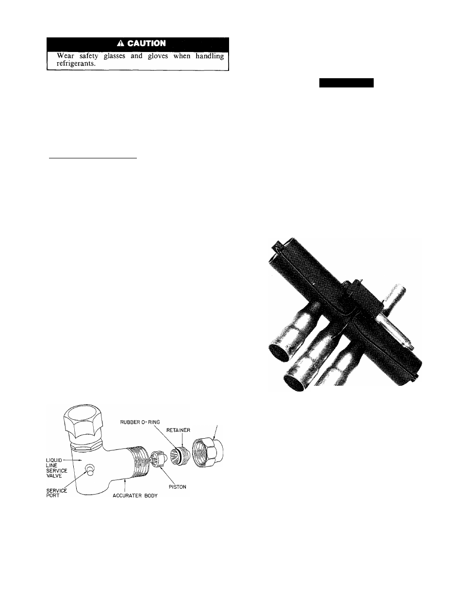
REVERSING VALVE — (See Fig. 24.) In heat pumps,
changeover between heating and cooling modes is
accomplished with a valve that reverses flow of refrig
erant in system. This reversing valve device is easy to
troubleshoot and replace. The reversing valve solenoid
can be checked with power off with an ohmmeter. Check
for continuity and shorting to ground. With control
circuit (24 v) power on, check for correct voltage at
solenoid coil. Check for burned or overheated solenoid.
Fig. 24 — Reversing Valve
With unit operating, other items can be checked, such
as frost or condensate water on refrigerant lines.
The sound made by a reversing valve, as it begins or
ends defrost, is a loud whooshing noise, as reversing
valve reverses, and pressures in system equalize. An
experienced service person detects this sound and uses it
as a valuable troubleshooting tool.
Using a remote measuring device, check inlet and outlet
line temperatures. Do not touch lines. If reversing valve
is operating normally, inlet and outlet temperatures on
appropriate lines should be close. Any difference would
be due to heat loss or gain across valve body. Tempera
tures are best checked with a remote reading electronic-
type thermometer with multiple probes. Route thermo
couple leads to inside of coil area through service valve
mounting plate area underneath coil. Figures 25 and 26
show test points on reversing valve for recording tempera
tures. Insulate points for more accurate reading.
17