Safety considerations, Service, A caution – Carrier 38E User Manual
Page 3: Caution
Attention! The text in this document has been recognized automatically. To view the original document, you can use the "Original mode".
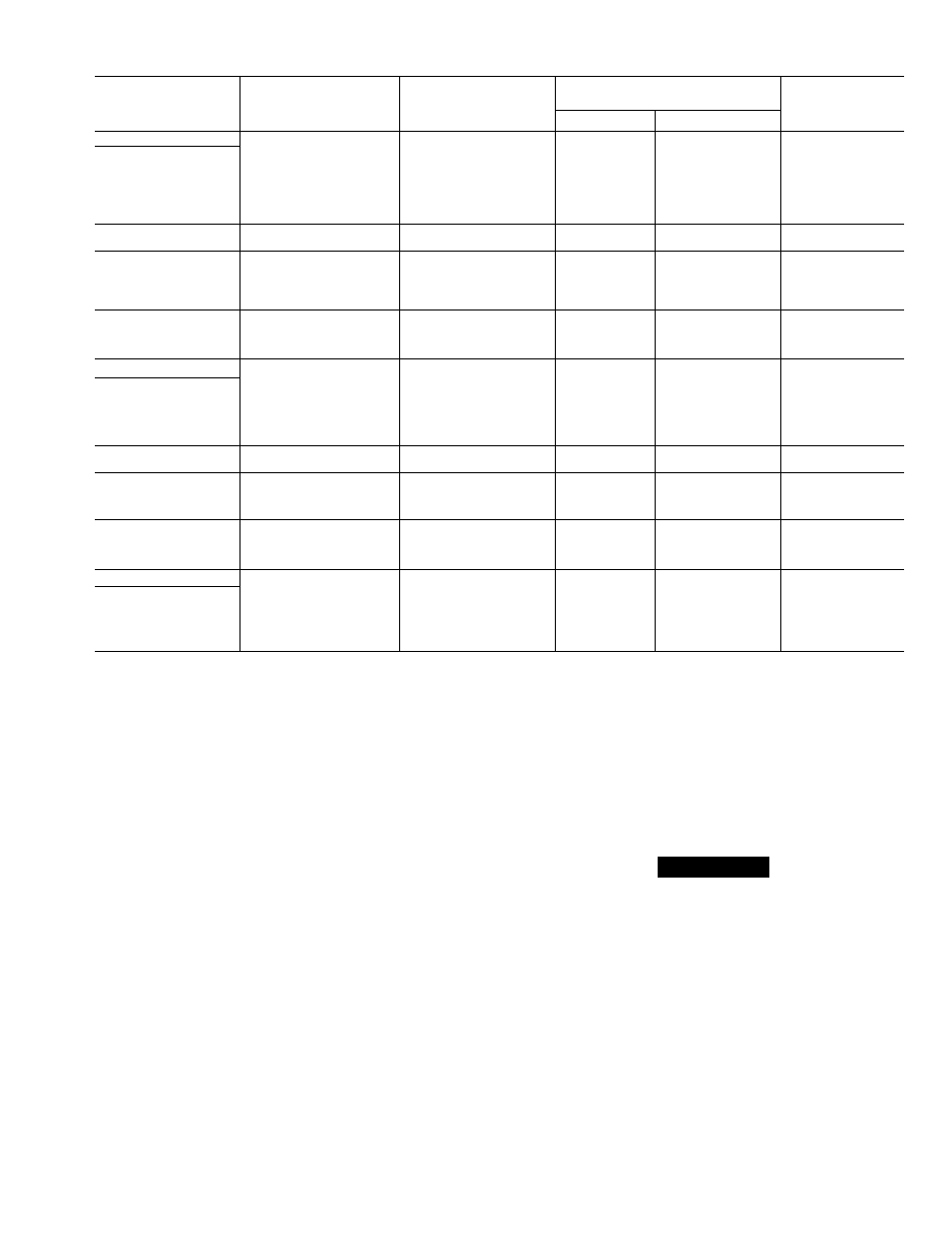
Table 5 — Heat Pump Specifications
OUTDOOR
UNIT
MODEL NO.
38-
ORIGINAL
COMPRESSOR
MODEL
REPLACEMENT
COMPRESSOR
MODEL
OIL CHARGE
REFRIG
CHARGE*
(R-22)
Initial
Recharge
QH
015
REZ3-0125-PFV
50QT662300
24
20
5.3
018
H22B173ABCA
38QF663300
40
37
5.5
024
CRC2-0175-PFV
38VH 660303
55
52
7.8
030
AV5532E
50SR661333
54
50
7.8
036
AV5535H
50SR661336
54
50
7.9
042 .
AV5542H
50SR661330
54
50
11.0
048
AV5546H
50SR661331
54
50
12.5
060
WD60000AA
WD6051AA
76
74
14.1
060341
H23A563ABCA
—
55
50
14.0
030
AV5532E
50SR661415
54
50
7.8
036
AV5535E
50SR661413
54
50
7.9
042
AV5542E
50SR661414
54
50
11.0
048
AV5546E
50SR661500
54
50
12.5
060
WY6000AA
WY6051AA
76
74
14.1
036
AV5535E
50SR661623
54
50
7.9
042
AV5542E
50SR661624
54
50
11.0
048
AV5546E
50SR661622
54
50
12.5
060
WH6000AA
WH6051AA
76
74
14.1
ON
015
REZ3-0125-PFV
38QB662301
24
20
3.6
018
AB5519H
50SR661311
32
28
4.1
024
MD2315GG
MD2364GE
46
44
5.6
030
MD3215GG
MD3264GE
46
44
6.1 . ,
036
MD3515GG
MD3564GE
46
44
8.9
042
AV5542E
50SR661330
54
50
9.5
048
PC5316BD
PC5366HD
76
72
9.7
060
PC6016BD
PC6066ED
76
72
10.8
036
MF3513GB
MF3563GE
46
44
8.9
042
AV5542E
50SR661330
54
50
9.5
048
PY5316AD
See Note t
76
72
9.7
060
PY6016BD
PY6066EF
76
72
10.8
036
MH3513GB
MH3563GE
46
44
8.9
042
PH4616AD
PH4666HD
76
72
9.5
048
PH5316AD
PH5366HD
76
72
9.7
060
PH6016BD
PH6066EF
76
72
10.8
QS
018
AB5515H
50SR661301
32
28
6.8
024
JD2200AA
JD2251AA
50
46
7.5
030
JD2800AA
JD2851AA
50
46
8.5
036
JD3300AA
JD3300AA
50
46
10.6
042
CRJ3-0300-PFV
38EB660301
55
51
11.5
'Factory refrigerant charge is adequate when indoor unit and outdoor unit are the same
size and are connected with 25ft or less of field tubing of recommended size orCarrier
accessory tubing. For tubing requirements beyond 50ft, consult Carrier distributor.
NOTE: Originally an extended voltage compressor.
Select
replacement
compressor
forvoltage-required:
tPF5366HD (200-3-60), PG5366HD (230-3-60).
SAFETY CONSIDERATIONS
Service and repair of these units should be attempted
only by trained service technicians familiar with Carrier
Standard Service Instructions.
All equipment should be installed in accordance with
accepted practices and in compliance with all national
and local codes.
Power should be turned off when servicing or repair
ing electrical components. Extreme caution should be
observed when troubleshooting electrical components
with power on. Observe all warning notices posted on
equipment.
Refrigeration system contains refrigerant under
pressure. Extreme caution should be observed when
handling refrigerants. Wear safety glasses and gloves to
prevent personal injury. During normal system opera
tion, some components are hot and can cause burns.
Rotating fan blades can cause personal injury. Appro
priate safety considerations are posted throughout this
manual where potentially dangerous techniques are
addressed.
SERVICE
Cabinet
— Certain maintenance routines and repairs
require removal of cabinet panels. All condensing units
and heat pump models of this series have same basic
design with only minor differences. See Fig. 1.
REMOVING LOUVERED CASING — (See Fig. 2.)
1. Turn off all power to unit.
2. Loosen screws around circumference of fan orifice.
3. Remove screws around circumference of basepan.
4. Remove screws along control box support brackets.
5. Carefully remove louvered casing.
A
CAUTION
Do not attempt to remove wire grille around coil.
Grille is integral part of coil structure and sup
ports coil.
REMOVING FAN ORIFICE — (See Fig. 3.)
1. Turn off all power to unit.
2. Remove screws holding grille on top of fan orifice.
3. Unplug wires from fan motor. Fan blades on certain
models may have to be removed. Refer to Service —
Electrical.
4. Remove screws holding fan orifice to wire grille and
control box.
5. Remove fan orifice.
ELECTRICAL BOX ACCESS — (See Fig. 1.)
1. Turn off all power to unit.
2. Remove screws holding box cover.