A warning – Carrier 38E User Manual
Page 18
Attention! The text in this document has been recognized automatically. To view the original document, you can use the "Original mode".
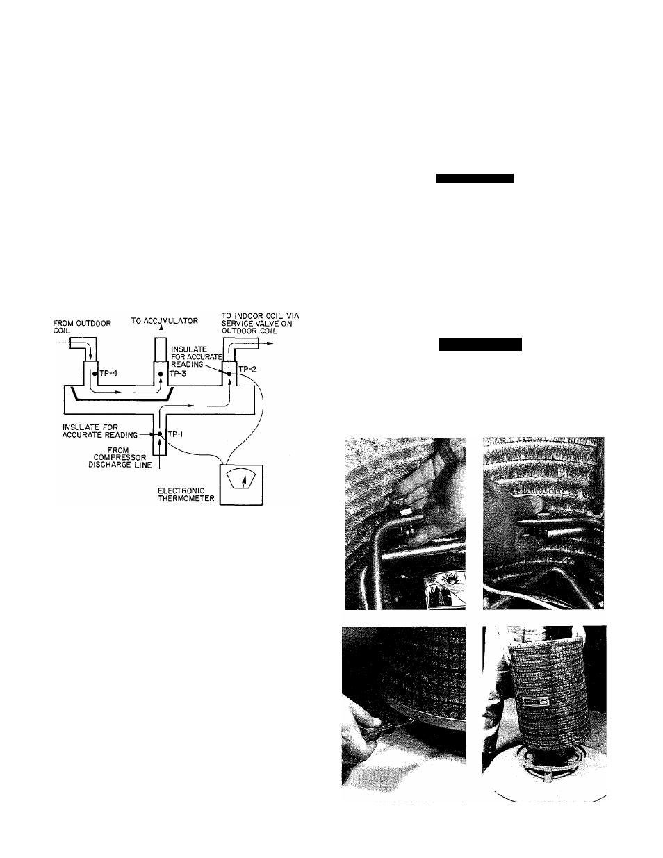
TO OUTDOOR
COIL
TP-4
FROM INDOOR COIL VIA
SERVICE VALVE ON
OUTDOOR COIL
TO
ACCUMULATOR
TP-3
TP-2
J
TP-1
FROM
COMPRESSOR
DISCHARGE LINE
TP = Test Point
TP-2 and TP-3 Cool or cold, may have condensation or frost on both lines
entering valve body, 5F to 10F maximum temperature difference across
normally operating valve.
TP-1 and TP-4 Hot, 5 F to 10 F maximum temperature difference across
normally operating valve.
Fig. 25 — Reversing Valve (Cooling Mode or
Defrost Mode, Solenoid Energized)
TP = Test Point
TP-1 and TP-2 Hot, 5F to 10F maximum temperature difference across
normally operating valve.
TP-3 and TP-4 Cool or cold, may have condensation or frost on both lines
into valve body, 5F to 10 F maximum temperature difference across
normally operating valve.
Fig. 26 — Reversing Valve (Heating Mode
Solenoid De-Energized)
If valve is defective: Shut off all power to unit. Some
smaller sizes may require coil to be removed to gain access
to reversing valve. See appropriate coil removal section.
Remove all charge from system.
Remove solenoid coil from valve body. Remove valve
by cutting it from system with tubing cutter. Repair
person should cut in such a way that stubs can be easily
rebrazed back into system. Do not use hacksaw. This
introduces chips into system that cause failure. After
defective valve is removed, wrap it in wet rag and care
fully unbraze stubs. Save stubs for future use. Because
defective valve is not overheated, it can be analyzed for
cause of failure when it is returned.
Braze new valve onto used stubs. Keep stubs oriented
correctly. Scratch corresponding matching marks on old
valve and stubs, and new valve body, to aid in lining up
new valve properly. When brazing stubs into valve,
protect valve body with wet rag to prevent overheating.
Use slip couplings to install new valve with stubs back
into system. Even if stubs are long, wrap valve with a wet
rag to prevent overheating.
After valve is brazed in, check for leaks. Evacuate and
charge system. Operate system in both modes several
times to be sure valve functions properly.
COIL REMOVAL — (See Fig. 27.) Coils on this family
of units are ea.sy to remove if required for compressor
removal, or to replace coil. Shut off all power to unit.
Remove refrigerant from system through service valves.
A CAUTION
Wear safety glasses and gloves when handling refrig
erants. If unit is equipped with a louvered casing,
refer to Cabinet Servicing for casing removal
procedure.
1. Remove discharge grille by removing 3 (015-030) or
6 (036-060) screws.
2. Remove control box cover (3 screws).
3. Remove fan/motor/orifice assembly by removing, 4
screws (2 in top of control box). Prior to lifting out
assembly, unplug motor wires from base of motor.
A WARNING
Avoid possibility of fire and personal injury by
cutting tubing.
4. Use midget tubing cutter to cut liquid and vapor lines
at both sides of coil. Cut in convenient location for
easy reassembly with copper slip couplings.
Fig. 27 — Removing Outdoor Coil
18