A caution – Carrier 38E User Manual
Page 8
Attention! The text in this document has been recognized automatically. To view the original document, you can use the "Original mode".
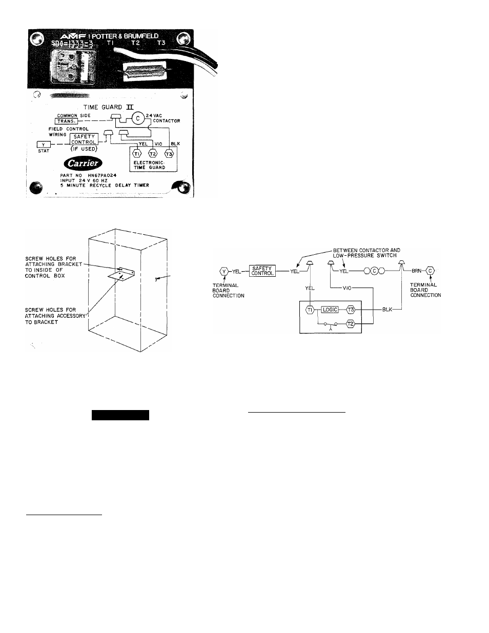
Tl
Т2
3
SEC
OPERATING
TIME
5MIN-
BLK DENOTES CLOSED CONTACTS
TIME GUARD II SEQUENCE CHART
ACCESSORY TIME GUARD II DEVICE
CUT YELLOW WIRE
-CONTROL
BOX
MOUNTING ACCESSORY TIME GUARD II
ON MODEL 38QH,QS,QN
NOTE: When accessory Time Guard II is used with accessory Service Sentry control on
38QH,QN,QS units, refer to wiring instructions packed with Service Sentry control.
TIME GUARD II CONTROL WIRING
CONNECTIONS FOR 38QH,QN,QS UNITS
Fig. 8 — Solid-State Time Guard II Description
A
CAUTION
Wear safety glasses and gloves when working with
refrigerants. Apply heat with a torch to solder joint
and remove switch. Wear safety glasses when using
torch. Have quenching cloth available. Oil vapor in
line may ignite when switch is removed.
Braze in
1
/ 4-in. flare fitting and screw on replacement
pressure switch. Wear safety glasses, observe all safety
precautions.
High-Pressure Switch — Located on discharge line,
protects against high discharge pressures caused by such
events as overcharge, condenser fan motor failure, system
restriction, etc. It opens on pressure rise at about 425 psi.
If system pressures go above this setting during abnormal
condition, switch opens. Do not attempt to simulate
these system abnormalities, as high pressures pose a
serious safety hazard. High-pressure switch is also
checked with an ohmmeter similar to checking low-
pressure switch. If system pressure is below 425 psi, switch
shows continuity. It is replaced in same manner as low-
pressure switch. Observe all safety precautions.
Liquid Line Pressure Switch — Located on liquid line,
used in heat pump only. Function is similar to con
ventional low-pressure switch. Because heat pumps
experience very low suction pressures during normal
system operation, a conventional low-pressure switch
cannot be installed on suction line. Switch is installed
in liquid line instead and acts as loss-of-charge protector.
It operates identically to low-pressure switch except it
opens at 5 psi. Troubleshooting and removing this switch
is identical to procedures used on other switches. Observe
same safety precautions.
DEFROST THERMOSTATS — Defrost thermostat
signals heat pump that conditions are right for defrost or
that conditions have changed to terminate defrost. It is a
thermally actuated switch clamped to liquid line to sense
its temperature. Normal temperature range is: closed at
27 - 5 F, open at 80 ± 5 F.
Since defrost thermostat is the heart of the defrost
system, its troubleshooting procedure is described below.
PRINTED-CIRCUIT CONTROL BOARD — Solid-
state defrost control used on 38QH,QN,QS heat pumps
replaces electro-mechanical timer and defrost relay found
on previous Carrier Chronotemp^“ defrost systems. De
frost control board can be set to check need for defrost