A caution, Refrigeration system – Carrier 38E User Manual
Page 15
Attention! The text in this document has been recognized automatically. To view the original document, you can use the "Original mode".
resistance from each reading. If any reading is within
± 20% of known resistance, motor is probably normal.
Usually a considerable difference in reading is noted if a
turn-to-turn short is present.
SYSTEM CLEAN-UP AFTER BURN-OUT
A
CAUTION
Turn off all power to unit before proceeding. Wear
safety glasses and gloves when handling refrigerants.
Acids formed as a result of motor burn-out can
cause burns.
Some compressor electrical failures can cause motor
to burn. When this occurs, byproducts of burn, which
include sludge, carbon and acids contaminate system.
If burn-out is severe enough, system must be cleaned
before replacement compressor is installed. The 2 types
of motor burn-out can be classified as mild or severe.
In mild burn-out, there is little or no odor detectable.
Compressor oil is clear or slightly discolored. An acid
test of compressor oil will be negative. This type of failure
is treated the same as mechanical failure. Liquid line
strainer should be removed and liquid line filter drier
installed.
In a severe burn-out, there is a strong, pungent, rotten
egg odor. Compressor oil is very dark. Evidence of burn
ing may be present in tubing connected to compressor.
An acid test of compressor oil will be positive. Complete
system must be reverse-flushed with refrigerant. Accu-
RateT“ or TXV must be cleaned or replaced. In a heat
pump, accumulator and reversing valve are replaced.
These components are also removed and bypassed during
reverse-flushing procedure. Remove and discard liquid
line strainer. After system is reassembled, install liquid
and suction line filter driers, run system for 2 hours.
Discard both driers, install new liquid line drier only.
COMPRESSOR REMOVAL AND REPLACEMENT
— Once it is determined that compressor has failed and
the reason established, compressor must be changed.
Shut off all power to unit. Remove all refrigerant
from system until pressure gage reads 0 psi.
A CAUTION
Wear safety glasses and gloves when handling refrig
erants. Disconnect electrical leads from compressor.
Disconnect or remove crankcase heater. Remove
compressor holddown bolts.
Cut compressor from system with tubing cutters. Do
not use brazing torch for compressor removal. Oil vapor
may ignite when compressor is disconnected. Scratch
matching marks on stubs in old compressor. Make
corresponding marks on replacement compressor. Use
torch to remove stubs from old compressor and to re
install them in replacement compressor. Use copper
couplings to tie compressor back into system. Wear safety
glasses when using brazing torch. Evacuate system,
recharge, check for normal system operation.
Refrigeration System
REFRIGERATION CYCLE — In a refrigerant system,
refrigerant moves heat from one place to another. It is
useful to understand flow of refrigerant in a system.
In a straight cooling system, compressed hot gas leaves
compressor and enters condensing coil. As gas passes
through condenser coil it rejects heat and condenses into
liquid. The liquid leaves condensing unit through liquid
line and enters metering device at indoor coil. As it passes
through metering device, it becomes a gas-liquid mixture.
As it passes through indoor coil, it absorbs heat and
refrigerant is again changed to gas. The gas is returned
to compressor, where it is compressed to a hot gas, and
cycle repeats.
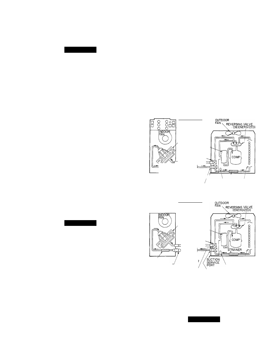
In a heat pump (see Fig. 19), the basic cycle is the same.
Reversing valve in system decides which coil, indoor or
outdoor, becomes evaporator or condenser. In heating
mode, indoor coil is condenser. It rejects heat into the
home after heat is absorbed by outdoor evaporator coil.
Thus, home is heated.
In cooling cycle, indoor coil becomes evaporator. It
absorbs heat from home and rejects it out-of-doors
through outdoor condenser coil. Thus, home is cooled.
A unique feature of the heat pump is that metering
devices are designed to meter refrigerant in one direction
of flow, and allow refrigerant to pass unhindered in other
direction. If indoor metering device is metering refrig
erant, outdoor device bypasses refrigerant and vice versa.
This allows both coils to serve a dual function.
HEATING CYCLE
INDOOR COIL
ACCUMULATOR
DISCHARGE SERVICE
PORTAT SERVICE
VALVE (HTG CYCLE)
STRAINER
ACCURATER'™
(BYPASSING)
HEAT PUMP
ACCESSORY
FILTER DRIER
(DUAL FLOW)
/SUCTION \ STRAINER
SERVICE \
OUTDOOR
PORT LIQUID LINE COIL
□ O
OoQ
□ o
Onn
o o
STRAINER
COOLING CYCLE
INDOOR COIL
ACCUMULATOR
SUCTION SERVICE
PORT AT SERVICE
VALVE (CLG CYCLE)
HEAT PUMP
ACCESSORY
FILTER DRIEF
(DUAL FLOW)
ACCU RATER
(METERING)
LIQUID LINE SERVICE PORT
AT SERVICE VALVE (CLG CYCLE)
ACCURATER
(BYPASSING)
OUTDOOR
COIL
LIQUID LINE
PRESSURE SWITCH
Fig. 19 — 38QN Heat Pump
Refrigerant Flow Diagrams
LEAK DETECTING — (See Fig. 20.) New installations
should be checked for leaks prior to complete charging.
A
CAUTION
Always wear safety glasses and gloves when handling
refrigerants.
15