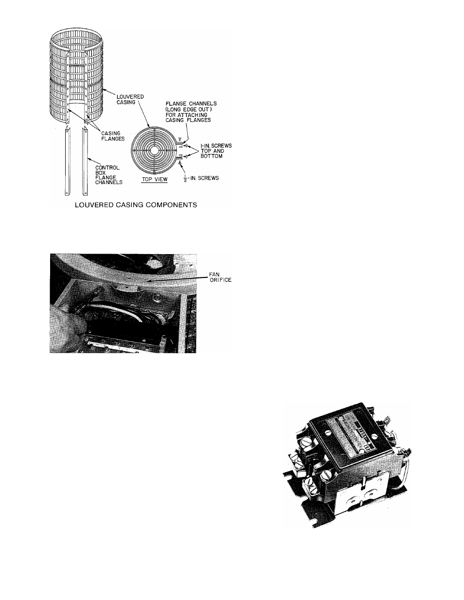
Fig. 2 — louvered casing assembly – Carrier 38E User Manual
Page 5
Attention! The text in this document has been recognized automatically. To view the original document, you can use the "Original mode".
TOP COVER
SCREWS
C
BASEPAN FLANGE
ATTACHING CASING TO TOP COVER
AND BASEPAN
Fig. 2 — Louvered Casing Assembly
Fig. 3 — Removing Orifice Fan
Electrical
— Exercise extreme caution when work
ing on any electrical components. Shut off all power
to system prior to troubleshooting. Some trouble
shooting techniques require power to remain on. In
these instances, exercise extreme caution to avoid
danger of electrical shock. ONLY TRAINED SERVICE
PERSONNEL SHOULD PERFORM ELECTRICAL
TROUBLESHOOTING.
CONTACTORS — (See Fig. 4.) Contactor provides
means of applying power to unit using lower power
(24 v) from transformer in order to power the contactor
coil. Depending on unit model, you may encounter
single-, double- or triple-pole contactors to break power.
One side of the line may be electrically hot, so extreme
caution must be exercised when troubleshooting.
The contactor coil for these and most residential
models of condensing units and heat pumps is powered by
24 vac. If contactor does not operate:
1. With power off, check whether contacts are free to
move. Check for severe burning or arcing on contact
points.
2. With power off, use ohmmeter to check for continuity
of coil. Disconnect leads before checking. A low-
resistance reading is normal. Do not look for a specific
value as different part numbers used will have different
resistance values.
3. Reconnect leads and apply low-voltage power to
contactor coil. This may be done by leaving high-
voltage power to outdoor unit off, and by turning
thermostat to heat or cool. Check voltage at coil with
voltmeter. Reading should be between 20 - 30 volts.
Contactor should pull in if voltage is correct and coil
is good. If contactor does not pull in, change
contactor.
4. With high-voltage power off and contacts pulled in,
check for continuity across contacts with ohmmeter.
A very low or zero resistance should be read. Higher
readings could indicate burned or pitted contacts
which may cause future failures.
Fig. 4 — Contactor