A caution – Carrier 38E User Manual
Page 11
Attention! The text in this document has been recognized automatically. To view the original document, you can use the "Original mode".
capacitor. Fan motor is equipped with thermal overload
device in motor windings which may open under adverse
operating conditions. Allow time for motor to cool so
device can reset. Further checking of motor can be done
with an ohmmeter. Set scale on R x 1 position, check
for continuity between 3 leads. Replace motors that show
an open circuit in any of the windings. Place one lead of
ohmmeter on each motor lead. At same time, place
other ohmmeter lead on motor case (ground). Replace
any motor that shows resistance to ground. Obviously
any motor that shows signs of arcing, burning or over
heating should be suspect and replaced.
SERVICE SENTRY CONTROL BOARD — Service
Sentry control provides immediate warning when out
door heat pump requires servicing. It turns on indoor
thermostat light if compressor doesn’t operate for either
heating or cooling. This enables owner to obtain speedy
heat pump service during heating season, reducing
supplementary electric heat costs, and during cooling
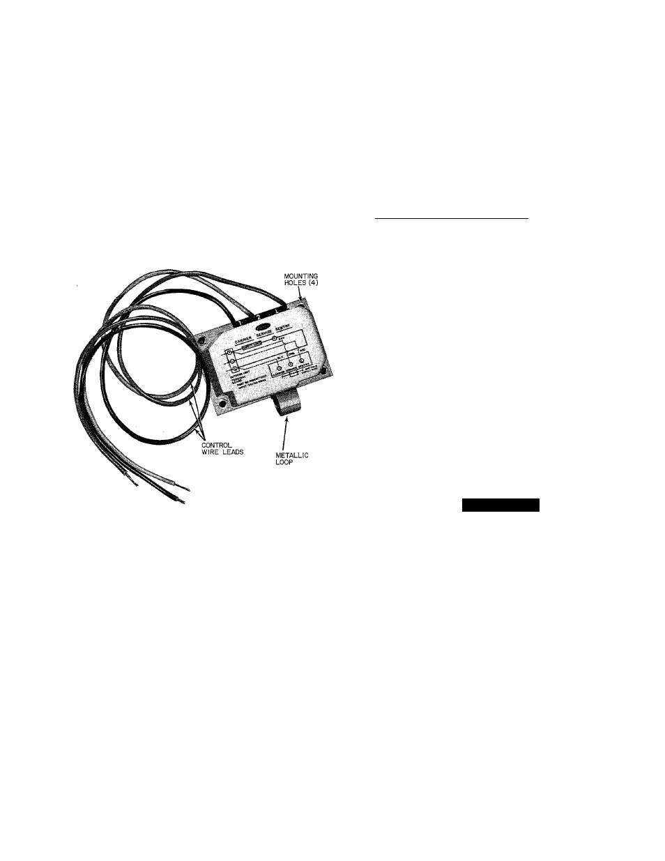
.season, reducing period of heat discomfort. Fig. 14.
Fig. 14 — Service Sentry Control
Refer to Fig. 15 for wiring connections when Service
Sentry and solid-state Time Guard II accessories are used.
The Service Sentry is an accessory device. On heat
pump DL and CD option packages, a slightly different
version of Service Sentry is installed as standard equip
ment. It functions almost identically to accessory Service
Sentry except that it locks out compressor under certain
adverse operating conditions. System is manually reset by
shutting it off at thermostat subbase, then turning it back
on. If adverse condition is corrected, system restarts.
One example of an adverse condition would be if
system is located in a desert climate where high operating
temperatures may cause system to shut down on the high-
pressure switch, or on the compressor internal overload.
Service Sentry Requires 2 Inputs:
1. It must sense a 24-v input from thermostat. As thermo
stat calls for heating or cooling, it supplies 24 v to
Service Sentry device.
2. A current transformer (or induction loop) similar to
a clamp-on ammeter senses current draw in the com
pressor lead. Induction loop must sense a minimum
current draw when thermostat is calling for heating
or cooling.
NOTES:
1. On a single-phase compressor, induction loop senses
current in common leg.
2. On a 3-phase compressor, induction loop senses
current in one of the pha.ses.
Troubleshooting Service Sentry device is easy. With
thermostat calling for heating or cooling and compressor
running, indoor thermostat light should be off If on,
check for wiring errors or replace the Service Sentry.
To check for correct operation, shut off circuit breaker
or disconnect switch to outdoor unit while it is running.
Signal light on thermostat should light. If this does not
occur, check for wiring errors or replace the Service
Sentry.
A CAUTION
If Service Sentry needs replacing, shut off all power
to unit before attempting repairs.
Use Service Sentry control with single-phase Carrier
heat pumps equipped with 24-v control circuit.
Connect black, orange and red pigtails (24 v) on Service
Sentry to outdoor unit control circuit terminal board.
See Fig. 15 and wiring diagram on unit. An extra control
wire is required between L terminals on outdoor unit,
indoor unit and thermostat subbase (the L terminal is
currently being added to outdoor and indoor unit termi
nal blocks). If units do not already have L terminal, splice
control wire between L terminals on Service Sentry and
thermostat subbase. Terminal L is labeled terminal X
on some thermostat subbases (all future subbases will
read terminal L).
Connect all field line power wires to unit in usual
manner. However, route one field line power supply wire
through metallic loop on bottom of Service Sentry, then
to normal unit connection. On 015 (230-1-60) and
018 (230-1-60) units, pass supply wire through metallic
loop twice, as shown in Fig. 14 and 15. On all other units,
pass supply wire through loop only once.
OUTDOOR THERMOSTATS — (See Fig. 16.) Out
door thermostat brings on stages of electric heat as out
door temperature and heat pump output drops. Setting
at which thermostat closes is variable, depending on
design of system. It is .set at time of installation and should
not be changed without good reason. Up to 2 outdoor
thermostats may be installed. Some systems may not
have any thermostat.
Although these devices are installed in control circuit
(24 v), turn off all power to unit before attempting to
troubleshoot thermostat.
Use a standard ohmmeter to check for continuity
through thermostat. If you suspect thermostat is out of
calibration, use calibrated electronic thermometer to
determine correct outdoor temperature. Insert a screw
driver blade in adjustment slot and turn thermostat
switch until it closes. Observe this using ohmmeter across
switch. Read temperature setting when switch clo.ses. It
should be close to reading observed using electronic
thermometer. Any setting within ± 5 degrees is
acceptable.
11