Carrier 542E User Manual
542e, Packaged heat pumps
Attention! The text in this document has been recognized automatically. To view the original document, you can use the "Original mode".
installation, operation,
and maintenance instructions
PACKAGED HEAT PUMPS
542E
Sizes 024 thru 060
& 542D060
NOTE TO INSTALLER: Leave these instructions with the
unit after installation.
NOTE: The installation of this unit must conform to the
guidelines presented in these unit Installation Instructions.
Read and become familiar with this publication before start
ing installation.
INTRODUCTION
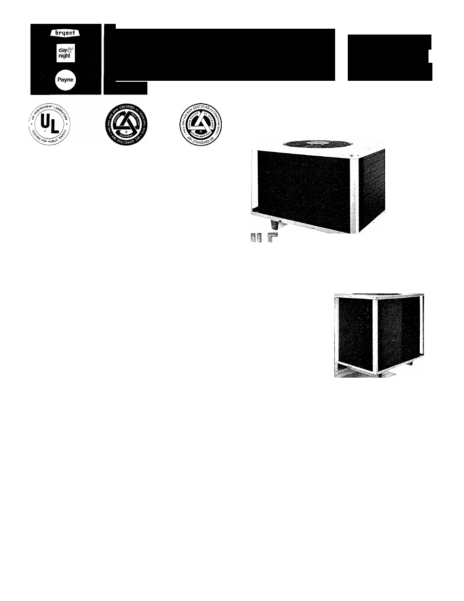
Models 542D and 542E Packaged Heat Pumps are fully self-
contained combinatipn heating/cooling units designed for
outdoor installation. Model 542E may be installed either on
a rooftop or ground-level slab. See Figure 1. Model 542D is
used with an accessory roof-mounting curb (P/N 304851-
302) and incorporates a down-discharge/return-air plenum
as an integral part of the unit. See Figure 2.
These units are factory-charged with R-22 refrigerant.
Installation is simple: connect condensate drain, air ducts,
high- and low-voltage.wiring, and install a field-supplied air
filter (except for model 542D which has factory-supplied air
filters).
All units can be connected into existing duct systems that
are properly sized and designed to handle an airflow of 350 to
450 ffimin per each 12,000 Btuh of rated unit capacity. See
Table I for indoor airflow requirements.
Accessory UL-listed, field-installed, supplemental electric
heat packages are available in a variety of KW and voltage
options. These electric resistance heaters mount inside the
unit blower compartment.
A full line of rooftop system accessories is available for field
installation. These accessories include plenums with facto
ry-supplied air filters (plenum not required with Model
542D), roof-mounting curbs, horizontal and downflow
economizers, barometric relief dampers, concentric diffuser
boxes, and flexible duct packages. Filter racks with air
filters are available for rooftop or ground-level installation.
NOTE: When installing any accessory item, see the Installa
tion Instructions packaged with the accessory.
IMPORTANT-READ BEFORE INSTALLING
1. This installation must conform with all applicable local
and national codes.
2. The power supply (volts, hertz, and phase) must corres
pond to that specified on unit rating plate.
3. The electrical supply provided by your utility must be
sufficient to handle the load imposed by this unit.
4. Refer to the 542D or 542E dimensional drawing for loca
tions of electrical inlets, condensate drain, duct connec
tions, and required clearances before setting unit in
place.
5. Styrofoam shipping blocks located between compressor
and divider panel and between accumulator and divider
panel must be removed. A failure to remove these blocks
can result in undesirable vibration noises being
transmitted into the conditioned space.
Cancels: 40542DP6-A
40542DP16-A
6/1/80
À
A79110
Figure 1—Model 542E
A79111
Figure 2—Model 542D060 Mounted on
Accessory Roof-Mounting Curb
GENERAL
Models 542D and 542E Packaged Heat Pumps have been
designed and tested in accordance with ARI Standards 240-
77 and 270-75, and these units are UL-listed.
This publication contains the following sections:
I.
Moving and Setting Unit in Place
II. Condensate and Defrost Disposal
HI. Duct Connections
IV. Electrical Connections
V. Preparing Unit for Startup
VI. Startup and Adjustments
VII. Sequence of Operation
VIII. Care and Maintenance
BDP Company, Division of Carrier Corp.
Document Outline
- 542E
- & 542D060
- Figure 2—Model 542D060 Mounted on Accessory Roof-Mounting Curb
- 542E REQUIRED CLEARANCE (Inches)
- 542E DIMENSIONS (Inches)
- Figure 3—542E Dimensional Drawing
- TABLE l-RATiNGS, PERFORMANCE, & RECOMMENDED FILTER SIZES
- TABLE ll-ELECTRICAL DATA-MODEL 542E-SIZES 024 THRU 042
- TABLE lll-ELECTRICAL DATA-MODELS 542E048, 542D060, & 542E060
- Figure 8—Partial Side'View With Compressor & Control Access Panels Removed (Model 542E036, 208V-230V—1)
- Figure 9—Field High-Voltage Connections
- TABLE IV-HEATING PERFORMANCE PRESSURES
- TABLE V-COOLING PERFORMANCE PRESSURES
- TABLE VI-AIR DELIVERY (FtVMin) AT INDICATED EXTERNAL STATIC PRESSURE & VOLTAGE*
- D. Unit Controls