Carrier 50MQ User Manual
Single-package heat pump units
Attention! The text in this document has been recognized automatically. To view the original document, you can use the "Original mode".
Number One
Air Conditioning
Maker
e
Division ot Carrier Corporatio
Syracuse New York
Single-Package Heat Pump Units
The 50MQ units are completely self-contained
cooling and heating systems with provision for
addition of accessory electric heaters. They are
air-to-air heat pumps designed for outdoor installa
tion. They may be connected into existing duct
systems which are properly sized and designed to
handle an air quantity of 400 to 500 cfm per ton
of cooling. Required connections include air ducts,
condensate drain, line and control power wiring.
Field-supplied filter must be installed in return air
duct. (See Table 1 for filter size.)
INSTALLER'S PRELIMINARY SURVEY
Step 1 — Inspect Equipment
— File claim with
shipping company if shipment is damaged or
incomplete.
Step 2 — Complete or Consider the Following
before installing the 50MQ unit;
a. Consult local building codes for special installa
tion requirements.
b. Provide sufficient space for coil air flow clear
ance, wiring, and servicing unit. (See Fig. 1.)
c. Locate unit where supply and return air ducts
can be conveniently brought out to unit duct
connections.
d. Unit may be placed with duct side as close to
building as condensate drain, top removal, duct
connections and power connections will permit
Position unit so water or ice from roof will not
drop directly on top of unit or in front of coil
e. Make provisions for condensate drainage and
defrost water disposal. See Mounting Pad and
Cooling Cycle Condensate Disposal.
f. Roof installation method for 50MQ will depend
on building construction and special require
ments of local building codes. Ensure roof will
support unit weight. See Mounting Pad for
details.
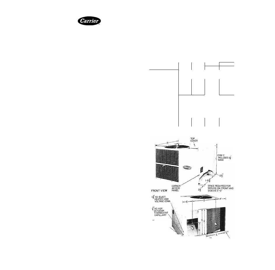
Table 1 — Installation Data (See Fig. 1.)
UNIT
50MQ022
50MQ027
50MQ032
50MQ037
OPER WT (lb)
315
330
340
353
DIMENSIONS
{ft-in») A
3-
6‘/4
B
3-
2
c*
2
- 3Ys
2
- 3%
2
- 3%
2-
7 %
D
1
-
1
OY
4
1
-
1
OV
4
1 - 1 0 ^ 4
1
-
1
OY
4
E
0
- 6 ^ 6
0
-
0
- óV.e
0
- 6V,6
F
0
-10“/,6
0
-10“/,
6
0
-10“/Ì6
0
-10“,(e
G
1
-- 1
6
1
— 1
6
1
— 1
^/] 6 1-
DUCT CONN.
S i d e ' b y - S i ( d €
R e c t a n g u
or
(ft-in.)
, , H
1
-
9%
Supply j
0
-
\ Q X
K
1
-
9 %
Return
1
-
7 %
FILTER SIZEt (in.)
Disposable
20
X 25
20
X
25
15
X 20
(2)
1 5
X
20
20
X 20
Permanent
15
X
20
20
X 20
20
X 20
20 X 25
‘Dimension "C"
t Recommended
includes 1 1/4-in built-in base support channels (2)
field-supplied filters are 1-in. thick
, ,,T
4-0 OVERHEAD AIR
SPACE REQUIRED
CHANNELS-2)
a OIAM HOLE-
CONTROL
WIRING CONN
l| DIAM HOLE-UNIT
LINE WIRING CONN „
REAR VIEW
■g
ID SIDE CONDENSATE
DRAIN FITTING
SPACE REQUIRED FOR SERVICE ON
REAR OF UNIT IS I'-O"
© Carrier Corporation 1974
O SUPPLY AIR
^ RETURN AIR
Certified dimension drawings available on request
Fig. 1 — Dimensions and Connections
Form No 50MQ-1SI
Document Outline
- e
- Single-Package Heat Pump Units
- INSTALLER'S PRELIMINARY SURVEY
- Step 2 — Complete or Consider the Following
- MOUNTING PAD
- DUCTWORK
- Step 5 — Connect Supply and Return Air Ductwork
- COOLING CYCLE CONDENSATE DISPOSAL
- ELECTRIC HEATER INSTALLATION
- ELECTRICAL DATA AND WIRING
- Operation of unit on improper line voltage or ; with e.xcessive phase unbalance constitutes abuse and is not covered by Carrier Warranty.
- CAUTION: Do not read evaporator temperature with Chargemaster valve open.