A caution – Carrier 38E User Manual
Page 10
Attention! The text in this document has been recognized automatically. To view the original document, you can use the "Original mode".
Reading on voltmeter should indicate zero volts.
This step ensures defrost relay contacts have closed,
energizing supplemental heat and reversing valve
solenoid.
10. Unit should remain in defrost no longer than 10
minutes. Actual time in defrost depends on how
quickly speed-up jumper is removed. If it takes 3
seconds to remove speed-up jumper after unit has
switched to defrost, only 7 minutes of defrost cycle
remains.
11. After a few minutes in defrost (cooling) operation,
liquid line should be warm enough to have caused
defrost thermostat contacts to open. Check resistance
across defrost thermostat. Ohmmeter should read
infinite resistance, indicating defrost thermostat
has opened.
12. Shut off unit power and reconnect fan lead.
13. Remove jumper wire from speed-up terminal pro
tective cover and reinsert cover on speed-up termi
nals. Failure to remove jumper causes unit to speed
up operating cycles continuously.
14. Remove jumper between DFT and C terminals.
Reconnect defrost thermostat leads.
15. Replace control box cover. Restore power to unit.
If defrost thermostat does not check out following
above steps or incorrect calibration is suspected, check
for a defective thermostat as follows:
1. Follow steps 1 - 5 above.
2. Using thermocouple temperature measuring device,
route sensor or probe underneath coil (or other
convenient location). Attach to liquid line near defrost
thermostat. Insulate for more accurate reading.
3. Restart unit in heating.
4. Within a few minutes, liquid line temperature drops
within a range causing defrost thermostat contacts to
close. Temperature range is from 32 F to 22 F. Notice
temperature at which ohmmeter reading goes from
oc to 0 ohms. Thermostat contacts close at this point.
5. Remove protective cover from TP 1 and TP2 speed-up
terminals, insert jumper wire into protective cover,
reinsert protective cover on the speed-up terminals.
6. Unit changes over to defrost within
90
seconds
' (depending on timing cycle setting). Liquid line tem
perature rises to range where defrost thermostat
contacts open. Temperature range is from
75 F
to
85 F.
Resistance goes from
0
to
oc
when contacts open.
7. If either opening or closing temperature does not fall
within above ranges, or thermostat sticks in one
position, replace thermostat to ensure proper defrost
operation.
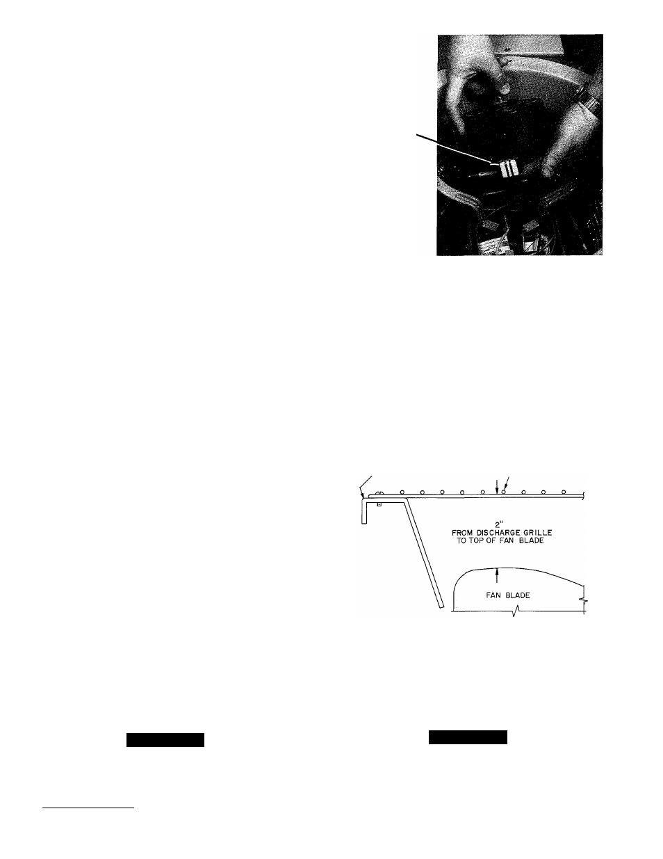
COLOR-CODED
TERMINAL BLOCK
Fig. 12 — Removing Outdoor Fan Motor
motor with 32 drops (16 drops per hole) of SAE 10 non
detergent oil at intervals described below:
a. Annually, when environment is very dirty, ambient
temperature is higher than 105 F (40 C), and average
unit operating time exceeds 15 hours a day.
b. Every 3 years, when environment is reasonably clean,
ambient temperature is less than 105 F (40 C) and unit
operating time averages 8 to 15 hours a day.
c. Every 5 years, when environment is clean, ambient
temperature is less than 105 F (40 C) and unit oper
ating time averages less than 8 hours a day.
After motor is lubricated, be sure fan prop is positioned
correctly on motor shaft. See Fig. 13.
DISCHARGE GRILLE
Fig. 13 — Condenser Fan Position
FAN MOTORS (See Fig. 12.) Fan motor powers fan
that draws air through outdoor coil to perform heat
exchange. Motors are totally enclosed to increase reli
ability. This also eliminates need for rain shield. Motors
are provided with color-coded terminal block to facilitate
removal. Oilers are provided on motor bearings. Adhere
to following schedule for fan motor lubrication.
Fan motors should present no problem in trouble
shooting. A motor with seized or tight bearings can
sometimes be saved or have its life extended by adding
oil to the bearings.
A CAUTION
Turn off all power to unit before servicing or replac
ing fan motor.
Fan Motor Bearings — Oiling holes are provided at each
end of condenser fan motor. Remove fan motor, lubricate
A
CAUTION
Be sure unit main power switch is turned off. Failure
to do so may result in electric shock, or injury from
rotating fan blade.
For suspected electrical failures, check for loose or
faulty electrical connections, or defective fan motor
10