A caution – Carrier 38E User Manual
Page 16
Attention! The text in this document has been recognized automatically. To view the original document, you can use the "Original mode".
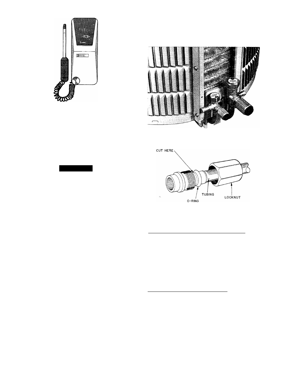
Fig. 20 — Leak Detector
If a system has lost all or most of its charge, system
must be pressurized again, up to approximately 1501b
minimum. This can be done by adding refrigerant, using
normal charging procedures. Or, it may be pressurized
with nitrogen (less expensive than refrigerant). Nitrogen
also leaks faster than R-22 and is not absorbed by refrig
eration oil. Nitrogen cannot, however, be detected by
leak detector.
A
CAUTION
Due to explosive pressures of nitrogen, it should
never be used without a pressure regulator on
the tank.
On the other hand, leaks in a system pressurized with
refrigerant can be spotted with a leak detector which
detects extremely small refrigerant leaks. This discussion
assumes that system is pressurized with either all refrig
erant or a mixture of nitrogen and refrigerant.
If system has been operating for some time, make first
check for a leak visually. Since refrigerant carries a small
quantity of oil, traces of oil at any joint or connection is
an indication the refrigerant is leaking at that point.
A simple and inexpensive method of testing for leaks is
to use soap bubbles. Any solution of water and soap
may be used.
Soap solution is applied to all joints and connections
in system. A small pinhole leak is located by tracing
bubbles in soap solution around leak.
Electronic leak detectors are now available for check
ing for leaks. These unquestionably represent the most
efficient and easiest method for checking for leaks.
There are various types of electronic leak detectors.
Generally speaking, they are all portable, most are light
weight, and consist of a box with several switches and a
probe or sniffer. Detector is turned on and probe is passed
around all fittings and connections in system. Leak is
detected by either a movement of a pointer on detector
dial, by a buzzing sound or a light.
In all instances, when a leak is found, system charge
must be hied down and leak repaired before final charging
and operation. After leak is repaired, evacuate system,
and correct refrigerant charge.
SERVICE VALVES (See Fig. 21.) Service valves pro
vide means for holding original factory charge in outdoor
unit prior to hookup to indoor coil. They also contain
gage ports for measuring system pressures, and provide
shutoff convenience for certain types of repairs.
Vapor line on all units and liquid line on condensing
units are connected to service valves by means of
Compatible Fitting. This mechanical-type fitting is also
used as a sweat fitting. Connections are made as follows:
Fig. 21 — Service Valves
COMPATIBLE FITTING
Fig. 22 — Carrier Compatible Fitting
CARRIER COMPATIBLE FITTING — (See Fig. 22.)
Mechanical Connection to Compatible Fitting — (Mate
one set of connections at a time.)
1. Loosen nut on Compatible Fitting one turn. Do not
remove.
2. Remove plug, be sure 0-ring is in groove inside
Compatible Fitting.
3. Cut tubing to correct length. Deburr and size properly,
4. Insert tube into Compatible Fitting until it bottoms.
5. Tighten nut until it bottoms on shoulder of fitting.
Keep tube bottomed in Compatible Fitting while
tightening nut.
Sweat Connection to Compatible Fitting — (Use refrig-
erant grade tubing.)
1. Remove locking nut, rubber 0-ring and Schrader
core from valve.
2. Cut tubing to correct length. Deburr and size properly.
3. Insert tube into Compatible Fitting.
NOTE: Wrap top and bottom of service valves in wet
cloth to prevent damage by heat. Solder with low-
temperature 430 F (221 C) silver alloy solder.
4. Replace Schrader core.
5. Evacuate or purge system with field-supplied
refrigerant.
16