USL JSD-100 Manual User Manual
Page 40
40
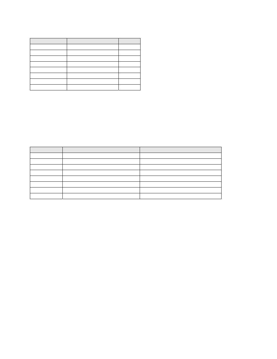
Channel Number DB25F PINS ( +, ‐, shield )
Speakers
1
2, 14, 1
Left
2
8, 20, 7
Right
3
5, 17, 4
Center
4
25, 12, 13
LFE
5
23, 10, 22
Ls
6
24, 11, 9
Rs
7
16, 3, 15
Lc/Lrs
8
19, 6, 18
Rc/Rrs
Eight Channel Analog Module Main Audio Outputs
The main outputs drive a Phoenix connector and a DB25M. The Phoenix output terminals are marked “Main
Outputs,” and the DB25M connector is marked “Monitor Outputs.” The DB25M typically drives a booth monitor
(such as the USL CM‐680), while the Phoenix terminals drive the auditorium amplifiers or crossover. These outputs
are connected together within the JSD‐100. The final two channels can be configured in the GUI as either Lrs/Rrs or
Lc/Rc. The DB25M connector uses the same THX® pin out as the eight channel analog input. The USL supplied
ferrite block should be clipped on to the cables adjacent to the connectors to comply with FCC and CE emission
requirements.
Audio Channel Phoenix Main Output Pins (+, ‐, shield)
DB25M Monitor Output Pins (+, ‐, shield)
Left
1, 2, 3
2, 14, 1
Center
4, 5, 3
5, 17, 4
Right
6, 7, 8
8, 20, 7
LFE
9, 10, 8
25, 12, 13
Ls
11, 12, 13
23, 10, 22
Rs
14, 15, 13
24, 11, 9
Lrs/Lc
16, 17, 18
16, 3, 15
Rrs/Rc
19, 20, 18
19, 6, 18
Sixteen Channel Analog Module Main Audio Outputs
The main outputs drive a pair of Phoenix connectors, and a pair of DB25M connectors. The Phoenix output
terminals are marked “Main Outputs” and “Optional Outputs.” The DB25M connectors are marked “Monitor 1
Outputs” and “Monitor 2 Outputs.” The DB25M connectors typically drive a booth monitor, while the Phoenix
terminals drive the auditorium amplifiers or crossover. The corresponding Phoenix strips and DB25M connectors
are connected together within the JSD‐100.
The final two channels on the “main outputs” can be configured in the GUI as either Lrs/Rrs or Lc/Rc except if the
speaker configuration is 13.1. When the speaker configuration is 13.1, these two channels are always Lc/Rc. The
DB25M connectors uses the same THX® pin out as the eight channel analog input. The USL supplied ferrite block
should be clipped on to the cables adjacent to the connectors to comply with FCC and CE emission requirements.
The “optional outputs” can be configured as additional full range channels (for example, for 13.1 sound), or may be
configured as the outputs of the internal crossovers.
Note that the 16 channel analog output module supports crossovers. To allow for proper bypass operation, a
passive crossover is included. For full band operation, set all four DIP switches to OFF and set the MID and HIGH
trim pots to full counter‐clockwise. Adjust the LOW trim pot for the desired full range bypass audio level. See
section 7.5 for more information on adjusting the bypass crossover. Remember that the front panel fader also
affects output level when in bypass.