USL JSD-100 Manual User Manual
Page 13
13
After approximately 25 seconds, the format buttons will flash and then a single format LED will light. The
display should show the fader level and the selected format.
Press each of the format buttons, verifying that the corresponding LED lights and that the display changes
accordingly. Note that the format button LEDs for digital formats will flash when no digital input is provided.
Press the mute button verifying that its LED toggles each time the button is pressed.
Rotate the fader in each direction verifying that the fader numbers on the display change.
6.2
System Hardware Mounting, Grounding and Ventilation
The JSD‐100 is designed to mount in a standard 19 inch (482.6mm) rack and is two rack units high (3.5 inches,
137.8mm). The JSD‐100 should be mounted at “eye level” in the equipment rack for optimum display contrast and
visibility. We recommend vented panels (USL part number VP‐1) above and below the JSD‐100 whenever space
permits. Mounting the unit immediately above a major heat‐producing component, such as a power amplifier, is
not recommended. Equipment mounted immediately above the JSD‐100 should not be more than 9 inches
(225mm) deep to insure adequate airflow through the rear ventilation slots on the JSD‐100. The JSD‐100 includes
a three‐prong grounding plug and a three‐wire power cord to accommodate a safe ground path from the chassis to
the electrical system ground. Defeating this ground by removing the ground prong is not recommended.
6.3
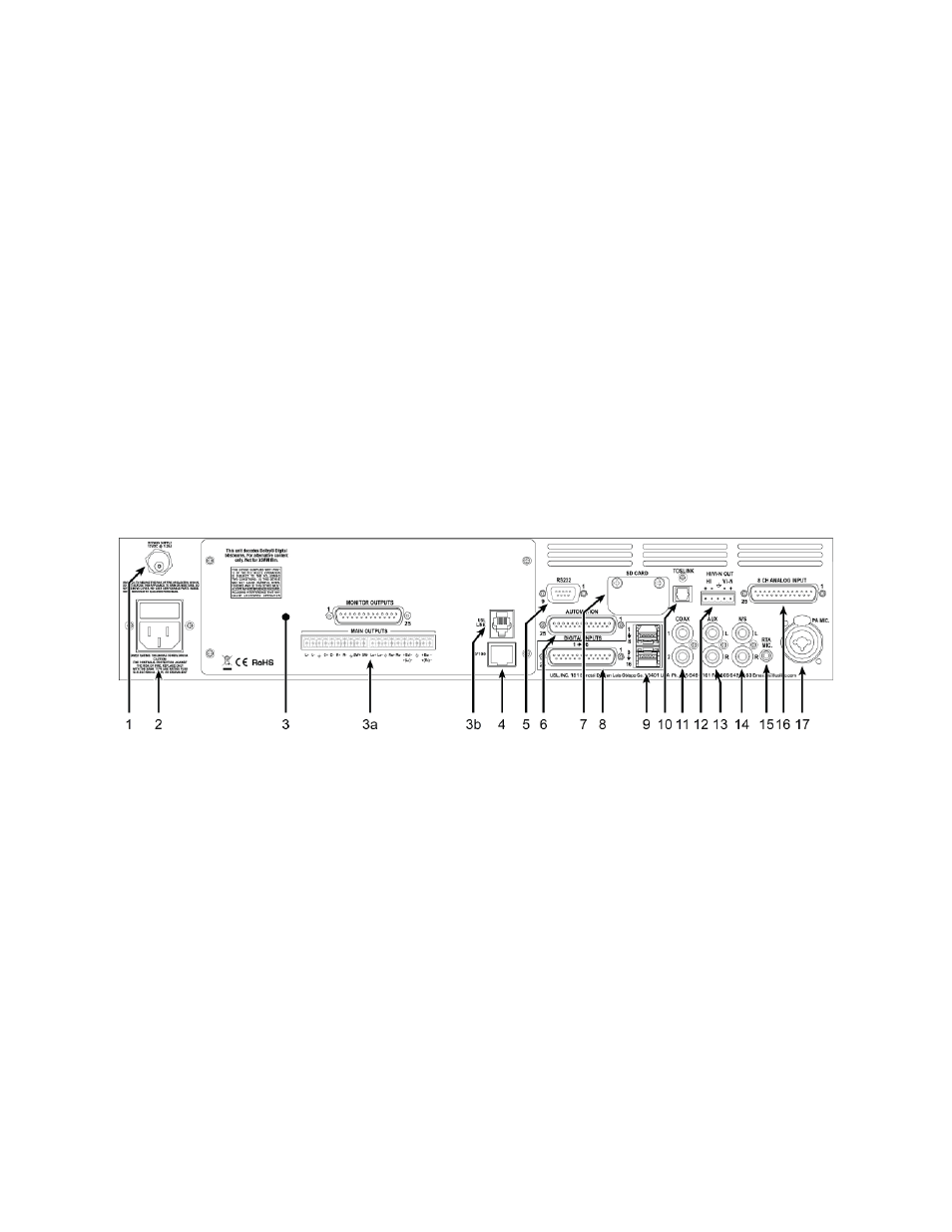
Eight Channel Analog Output Rear Panel Connections
A set of clip‐on ferrite “beads” is supplied with the JSD‐100. To insure the JSD‐100 continues to meet FCC and CE
radio emissions requirements, one of these beads should be clipped around each cable connected to the rear
panel of the JSD‐100 except for the TOSLINK, AC Power, and Bypass Power connection.
1. Bypass Power Supply – 12VDC at 1.25A.
2. Power entry Module – Accepts IEC‐type line cord from 100‐240VAC power source. Also contains a 500mA Slo‐
Blo 5x20mm fuse.
3. Eight Channel Analog Output Module – Other modules include 16 channel analog and 32 channel AES.
a. 8 Channel Analog Module provides six fixed outputs (L, C, R, LFE, Ls, Rs) and two that can be set up as
either Lc/Rc or Lrs/Rrs. Balanced line Phoenix and DB25M connectors are provided. The Phoenix
connector normally drives auditorium amplifiers and the DB25M connector normally drives a booth
monitor.
b. USL Link ‐ An RJ25 connector that provides an RS‐485 interface for remote volume control and other
functions.
4. Ethernet – Network communications with GUI, web browsers, automation, etc.
5. RS‐232 on a DE9F connector for communications with GUI or automation.
6. Automation DB25F Connector – A bidirectional port for receiving and sending automation pulses between the
JSD‐100 and other system components. 12 Control lines, 11 Status lines and +5V are provided. Standard pulse
to ground system.
7. SD Card – Stores a backup copy of unit configuration. Can also be used to transfer settings to another unit.
8. AES connector (DB25F) – Channels 1‐8 are standard. Channels 9‐16 require the optional DI‐80 module.
9. AES connectors (Dual RJ45s) – parallel connections to the DB25F above.