USL JSD-100 Manual User Manual
Page 32
32
8. Adjust the gain control (output trim) on the equalizer until a measured sound level of 85dB SPL or 82dB SPL for
surround channels is present.
9. Adjust the RTA gain to put the mid‐band level at 0dB.
10. Adjust the equalizer controls to put each frequency band within the curve limits As discussed above, the decay
time should be increased for more stable and precise measurement as you close in on the final equalization.
11. Turn off the generator.
12. Copy the equalizer settings to the next channel to be equalized using the Copy button. Then repeat the
process for the next channel.
LFE Equalization Procedure
The LFE or subwoofer channel uses a parametric equalizer instead of a graphic equalizer. When the LFE is selected
in the Equalizer window, the parametric equalizer adjustments become visible.
1. As with the other channels, start with the amplifier gain all the way down and the equalizer gain all the way
down.
2. Slowly bring up the amplifier gain control to full without exceeding 85dB SPL.
3. Adjust the equalizer gain control up until the RTA shows the subwoofer at the same level as the mid‐band
frequencies (0dB).
4. Adjust the parametric filter frequency to the center of the worst peak or dip in the frequency response.
5. Set the Q to 4, and then adjust the level control to take out the dip or peak. The Q can be increased to narrow
the correction or reduced to make the correction wider. Adjust the level, frequency, and Q for the best low
frequency response.
6. Select the output tab and click Generator under the center channel slider. At this point, the pink noise
generator should be driving both the LFE and center channels. Select the equalizer tab again.
7. Adjust the LFE gain and make minor adjustments to the LFE parametric filter to get a smooth frequency
response over the transition into the LFE frequency range. It may be necessary to flip the phase of the LFE
speaker. The phase can be changed on the Outputs tab using the Invert button under the LFE output level
control.
8. Finally, on the equalizer tab, adjust the LFE gain so the LFE is 10dB above the mid‐range frequencies.
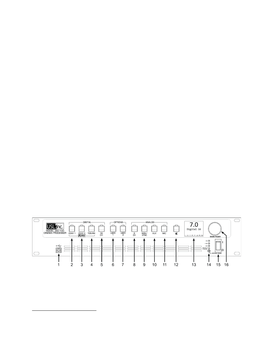
System Operation
The JSD‐100 is controlled by the digital cinema server in most installations. Control is also available from the front
panel.
1. USB Connector for communications. Select on the user interface
2. COAX 1 – Rear Panel RCA type connector for PCM or optional Dolby Digital®
7
decoding.
3. COAX 2 – Rear Panel RCA type connector for PCM or optional Dolby Digital® decoding.
4. TOSLINK – An optical fiber connection for PCM or optional Dolby Digital® decoding.
5. 16 CHANNEL DIGITAL – AES Balanced line inputs. The channels 1‐8 are standard. Channels 9‐16 require the
optional DI‐80 module.
6. USER 1 – allows the selection and configuration of any input and any settings.
7
Manufactured under license from Dolby Laboratories. Dolby and the double‐D symbol are trademarks of Dolby Laboratories.