USL JSD-100 Manual User Manual
Page 14
14
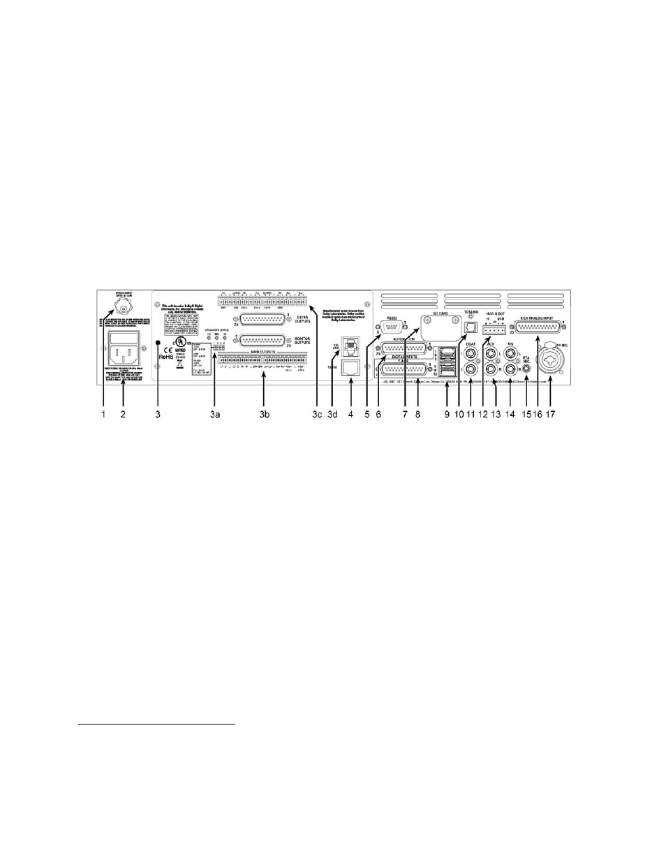
10. TOSLINK Port – Optical Fiber input for SPDIF (PCM) or optional Dolby Digital®
2
decoding.
11. COAX 1, COAX 2 ‐ RCA type connectors for SPDIF (PCM) or optional Dolby Digital®
decoding.
12. Hearing Impaired/Visual Narration Outputs.
13. AUX connectors – L and R analog inputs, 300mV sensitivity.
14. Non Sync (N/S) connectors – L and R analog inputs.
15. RTA microphone – 3.5mm stereo jack with +10V on the ring, designed for use with a powered electret
microphone.
16. 8 Channel Analog Input on DB25F – Balanced line inputs. Six channels are fixed (L, C, R, LFE, Ls, Rs) and two
can be set up as either Lc/Rc or Lrs/Rrs.
17. Public Address Microphone – Dual connector with XLR and ¼” phone jack in the center.
6.4
Sixteen Channel Analog Output Rear Panel Connections (JSD‐100xA)
A set of clip‐on ferrite “beads” is supplied with the JSD‐100. To insure the JSD‐100 continues to meet FCC and CE
radio emissions requirements, one of these beads should be clipped around each cable connected to the rear
panel of the JSD‐100 except for the TOSLINK, AC Power, and Bypass Power connection.
1. Bypass Power Supply – 12VDC at 1.25A.
2. Power entry Module – Accepts IEC‐type line cord from 100‐240VAC power source. Also contains a 500mA Slo‐
Blo 5x20mm fuse.
3. Sixteen Channel Analog Output Module – Other modules include 8 channel analog and 32 channel AES.
a. Bypass crossover adjustments.
b. Main outputs cover the first 8 output channels. The Phoenix connectors normally drive the power
amplifiers, and the DB25M connectors drive the booth monitor.
c. Extra outputs cover the second 8 output channels.
d. USL Link ‐ An RJ25 connector that provides an RS‐485 interface for remote volume control and other
functions.
4. Ethernet – Network communications with GUI, web browsers, automation, etc.
5. RS‐232 on a DE9F connector for communications with GUI or automation.
6. Automation DB25F Connector – A bidirectional port for receiving and sending automation pulses between the
JSD‐100 and other system components. 12 Control lines, 11 Status lines and +5V are provided. Standard pulse
to ground system.
7. SD Card ‐ Stores a backup copy of unit configuration. Can also be used to transfer settings to another.
8. AES connector (DB25F) – Channels 1‐8 are standard. Channels 9‐16 require the optional DI‐80 module.
9. AES connectors (Dual RJ45s) – parallel connections to the DB25F above.
10. TOSLINK Port – Optical Fiber input for SPDIF (PCM) or optional Dolby Digital®
3
decoding.
11. COAX 1, COAX 2 ‐ RCA type connectors for SPDIF (PCM) or optional Dolby Digital®
decoding.
12. Hearing Impaired/Visual Narration Outputs.
2
Manufactured under license from Dolby Laboratories. Dolby and the double‐D symbol are trademarks of Dolby Laboratories.
3
Manufactured under license from Dolby Laboratories. Dolby and the double‐D symbol are trademarks of Dolby Laboratories.