Isobus job computer : ic18 sprayer, Chapter 3 – main setup in sprayer mode, Main setup mode menu structure – TeeJet IC18 SPRAYER JOB COMPUTER User Manual
Page 21
15
98-05204 R1 US
ISOBUS Job Computer : IC18 Sprayer
OVER
VIE
W
SE
TUP
APPENDIX
GE
TTING ST
AR
TED
OPER
ATION
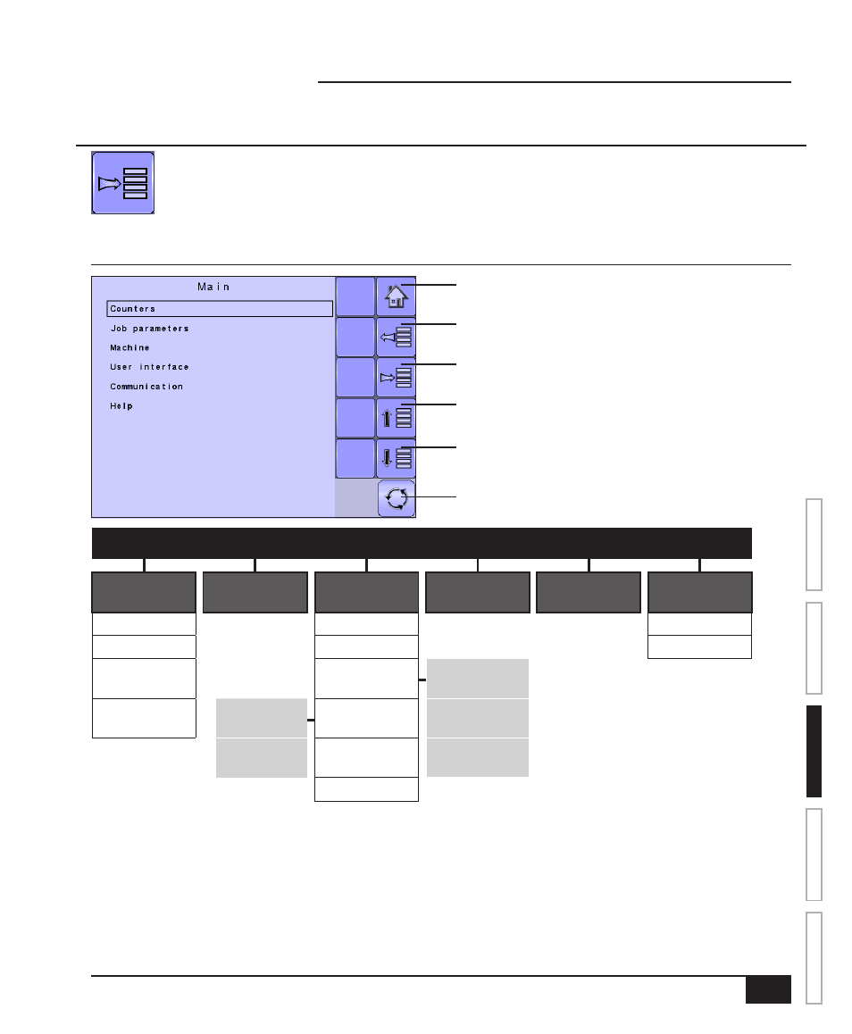
Figure 3-1: Main Setup Screen
Home Key
Back One Screen
Up One Option
Down One Option
Master Screen Key
Forward One Screen
MAIN SETUP MODE MENU STRUCTURE
|
|
|
|
|
|
Counters
(pages 18-21)
Job Parameters
(pages 22)
Machine
(pages 23-34)
User Interface
(pages 35-36)
Communication
(pages 37)
Help
(pages 38-41)
Trip
Filling
Diagnostic
Campaign
Operation
About
Total
Implement
parameters
– Section width
Export Counters
Implement
speed sensor
– Calibrations
Nozzle preset
setup
Flow sensor
Alarm
configurations
Regulation
parameters
OEM
The OEM setup menu is password protected and the settings in this menu are directly related to the fitted OEM equipment. Refer to the IC18
Sprayer/NH3 OEM Setup Manual
for information regarding OEM settings.
CHAPTER 3 – MAIN SETUP IN SPRAYER MODE
Main Setup Mode configures the Counters, Job Parameters, Machine, User Interface, Communication
and Help options.
NOTE: The menu structure on your display might vary from the one displayed in this User Manual
depending on the virtual terminal being used.