5 programming e&m signaling types, 5 programming e&m signaling types -6, 1 jumper switch settings -6 – Carrier Access Access Bank II SNMP User Manual
Page 109: 1 jumper switch settings, Table 11-2: jumper connections by type and mode
4-Wire E&M/TO Configuration
11-6
9/24/01
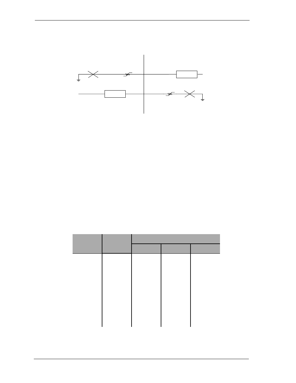
Figure 11-6: E&M Signaling Type 5
11.5 Programming E&M Signaling Types
11.5.1 Jumper Switch Settings
E&M signaling types I, II, IV and V (see Figure 11-3, Figure 11-4, Figure 11-5, and Figure 11-6) are
configured by jumpers J1, J2 and J3 located on each channel. Because the signaling types are config-
ured for each channel individually, different E&M types may be mixed on the same card. The entire
card, however, must operate in either Normal or Tandem mode, which is determined by the signaling
cable used (Section 11.7, Normal and Tandem Cables). Table 11-2 (which is also printed on the 4-
wire E&M back plate) shows the proper jumper connections for each signaling type and mode.
The jumpers are blocks that make several connections simultaneously. The entire block is moved
Table 11-2: Jumper Connections by Type and Mode
E&M
Type
Mode
Jumper Placement
J1
J2
J3
1
Normal
3-4
5
8-9
1
Tandem
1-2
5
10-11
2
Normal
3-4
6
7-8
2
Tandem
1-2
6
7-8
4
Normal
1-2
6
7-8
4
Tandem
1-2
6
7-8
5
Normal
1-2
5
8-9
5
Tandem
1-2
5
8-9
M-Lead
Detector
-48V
E-Lead
Detector
-48V
M
E
E&M Type 5
Normal Mode
(Terminating)
(Channel Equipment)
Tandem Mode
(Originating)
(Switching Equipment)