System configurations 3, Energy cutoff limit device 3, Ambient cutoff 3 – Reznor ADFH Parts Manuals User Manual
Page 3: Emperature limit 3, Automatic 3, Electrical components
Form P-ADF, P/N 270068 R1, Page 3
Model ADF/ADFH
System Configurations
(Sizes 300 and 500 have
a single blower; Sizes
700 and 1200 have dual
blowers.)
Burner/
Control
Section
Blower/
Motor
Section
Airflow
Burner/
Control
Section
Blower/
Motor
Section
Airflow
Airflow
Discharge
Burner/
Control
Section
Blower
Section
Airflow
Motor
Section
Burner/
Control
Section
Blower
Section
Airflow
Motor
Section
Airflow
Discharge
Airflow
Discharge
Airflow
Discharge
Model ADF
300/500/700/1200
with Horizontal Discharge
Model ADF
300/500
with Vertical Discharge
Model ADFH
300/500/700/1200
with Vertical Discharge
Model ADF
700/1200
with Vertical Discharge
On Model ADF Sizes 700
and 1200 with vertical dis-
charge, the extra cabinet
is required for space to
mount the blower motor.
On all Model ADFH sys-
tems, the extra cabinet is
required to keep the motor
out of the airstream of the
higher temperature dis-
charge air.
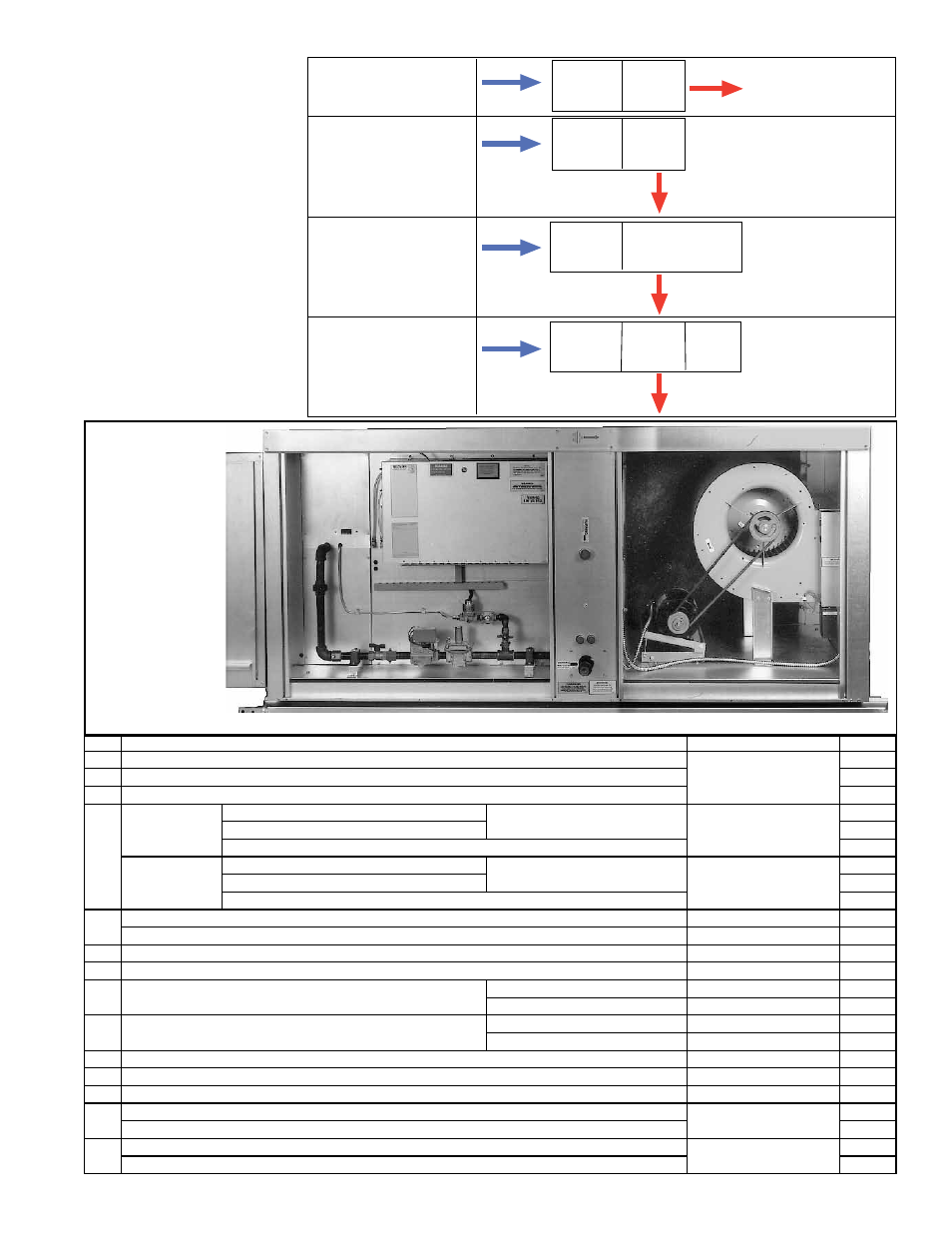
Electrical
Compartment
Burner / Gas Train / Electrical Compartment
Motor and Blower
Model ADF
300 showing
Compartments
Electrical
Components
CODE Description
Location
P/N
1
PC Board Assembly (circuit board with diagnostic lights, See Code 1A)
Electrical Compartment
151263
1A Replacement Light for PC Board Assembly (Code 1)
125189
1B Replacement Relay for PC Board Assembly (Code 1)
151271
2
Relay, SP-ST or
SP-DT, 24V Coil
Relay
Units manufactured after 8/11
Control Compartment
211411
Relay Socket Base
211415
Replacement Kit for units mfgd prior to 8/11 (replaces P/N's 14747, 98118, 103317)
263527
Relay, SP-ST or
Sp-DT, 120V Coil
Relay
Units manufactured after 8/11
Control Compartment
211414
Relay Socket Base
211415
Replacement Kit for units mfgd prior to 8/11 (replaces P/N's 103318 & 103319)
263530
3
Time Delay Relay (for freezestat bypass), T & B Agastat #VTM1ULA
Electrical Compartment
89661
Time Delay Relay (Low Fire), 24V Coil, Thermodisc #F12S20, Style 305005
Control Compartment
89254
4
Starter Relay, Essex #91-102006-13088, SPDT, 24V coil
Electrical Compartment
110656
5
Energy Cutoff Limit Device
Brnr/Cntrl Compartment
82414
6
Limit Switch, Automatic
ADF, 130°F
Blower Section
122856
ADFH, 170°F
Blower Section
57953
7
High Temperature Limit, Manual Reset
ADF, 135°F
Blower Section
122858
ADFH, 175°F
Blower Section
122990
8
High Ambient Cutoff, J/C #A19AAF-12C
Electrical Compartment
126170
9
Freezestat, J/C #19AAF-12C
Blower Compartment
126170
10 Firestat, Honeywell #L4029E1029, 200°F
Blower Discharge
42782
11
Low Air Pressure Switch, IS2-0211, set @ .25" w.c.
Electrical Compartment
203932
Low Air Pressure Switch Kit replaces P/N 86986, #FS4197-166 or PPS10175-3043
193806
12
High Air Pressure Switch, IS2-2075055F5193, set @ -.75" w.c.
Electrical Compartment
203933
High Air Pressure Switch Kit replaces P/N 86987, #FS4197-164 or PPS10175-3041
193807