0 dimensions and clearances, 1 dimensions, 2 clearances – Reznor X Unit Installation Manual User Manual
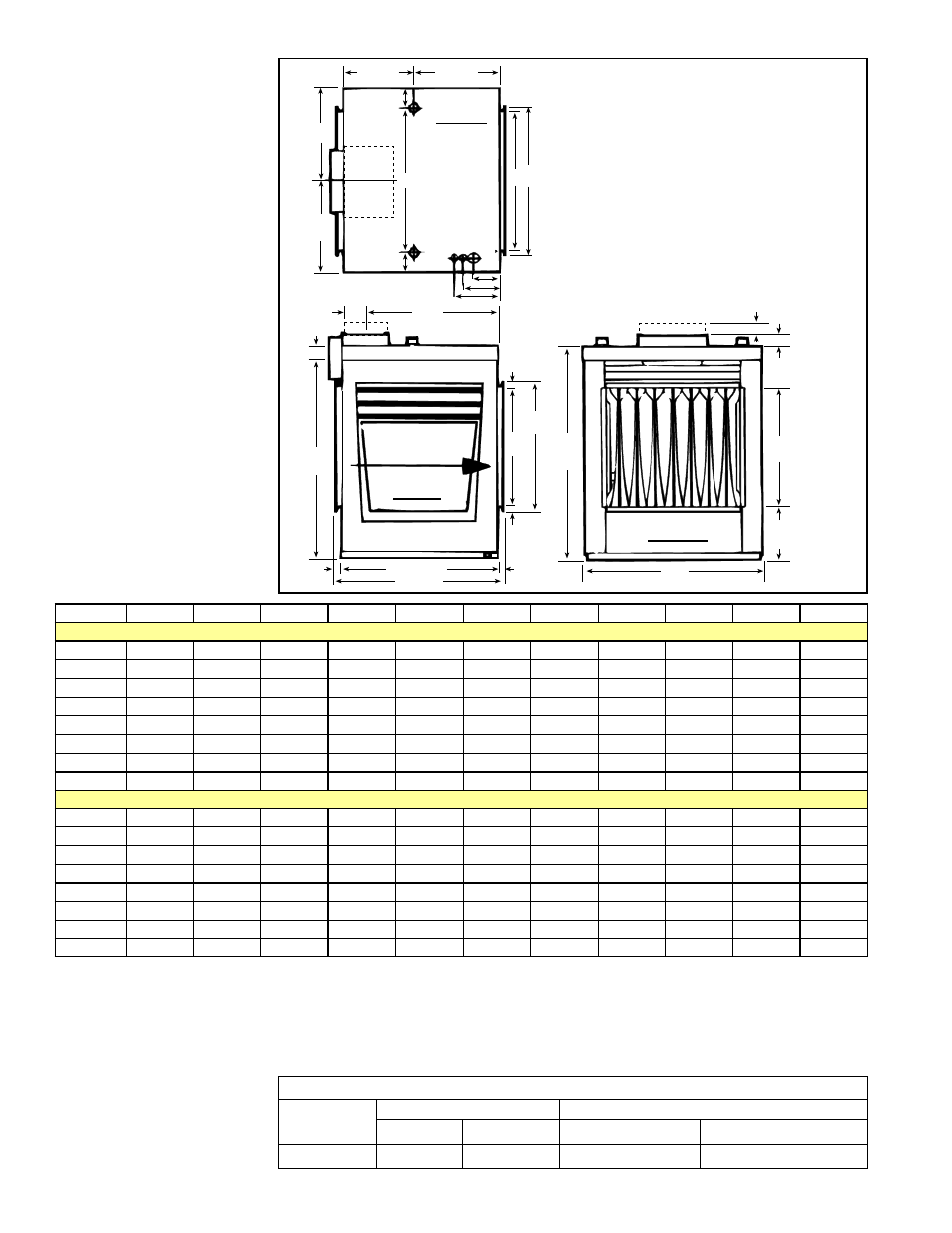
Page 6: Figure 5 - model x dimensions - inches (mm)
Form I-X, P/N 150491 R10, Page 6
4.0 Dimensions
and
Clearances
4.1 Dimensions
G
H
P
Q
B
A
15/16
(24)
15/16
(24)
24-1/8 (613)
26 (660)
3/4 (19)
18
(457)
19-1/2
(495)
3/4 (19)
Alternate Location
for Flue Collar
Airflow
2 (51)
1-5/8 (41)
18
(457)
8
(203)
J
J
K
D E
11-9/16
(294)
12-9/16
(319)
2-3/4 (70)
2-3/4 (70)
4 (102)
5-3/8 (137)
6-3/4 (171)
Electric Supply Thermost
at Connectio
n
Gas Connection
Top View
Left Side
Front View
(Standard Control &
Burner Access Side)
Size
A
B
D
E
G
H
J
K
P
Q
Flue
Dimensions (inches)
75
19-1/4
32-1/4
12-1/2
14
30-1/4
2
9-5/8
13-3/4
3-1/2
20-3/4
5" Round
100
19-1/4
32-1/4
12-1/2
14
30-1/4
2
9-5/8
13-3/4
3-1/2
20-3/4
6" Round
125
22
32-1/4
15-1/4
16-3/4
30-1/4
2
11
16-1/2
3-1/2
20-3/4
7" Oval
150, 175
27-1/2
32-1/4
20-3/4
22-1/4
30-1/4
2
13-3/4
22
3-1/2
20-3/4
8" Oval
200, 225
33
35-1/4
26-1/4
27-3/4
31-3/4
3-1/2
16-1/2
27-1/2
5
19-1/4
8" Round
250, 300
41-1/4
35-1/4
34-1/2
36
31-3/4
3-1/2
20-5/8
35-3/4
5
19-1/4
10" Oval
350
46-3/4
35-1/4
40
41-1/2
31-3/4
3-1/2
23-5/8
41-1/4
5
19-1/4
12" Oval
400
52-1/4
35-1/4
45-1/2
47
31-3/4
3-1/2
26-1/8
46-3/4
5
19-1/4
12" Oval
Dimensions (mm)
75
489
819
318
356
768
51
244
349
89
527
127 Round
100
489
819
318
356
768
51
244
349
89
527
152 Round
125
559
819
387
425
768
51
279
419
89
527
178 Oval
150, 175
699
819
527
565
768
51
349
559
89
527
203 Oval
200, 225
838
895
667
705
806
89
419
699
127
489
203 Round
250, 300
1048
895
876
914
806
89
524
908
127
489
254 Oval
350
1188
895
1016
1054
806
89
600
1048
127
489
305 Oval
400
1327
895
1156
1194
806
89
664
1187
127
489
305 Oval
FIGURE 5 - Model X
Dimensions - inches (mm)
4.2 Clearances
Required Clearances
Top
Sides
Bottom
Control
Opposite
To Combustibles To Non-Combustibles
6" (152mm) See Note 6" (152mm)
3" (76mm)
0
Clearance to combustibles is defined as the minimum distance from the heater to a
surface or object that is necessary to ensure that a surface temperature of 90°F above
the surrounding ambient temperature is not exceeded.
Clearance is also required to sides of furnace for combustion air space and for conve-
nient installation and burner control service.
NOTE: To have sufficient
space to remove the
drawer-type burner rack,
the clearance on the control
side of the furnace must be
the width of the furnace plus
6" (152mm).