0 maintenance and service (cont'd), 3 cleaning pilot and main burners, 4 cleaning the heat exchanger – Reznor X Unit Installation Manual User Manual
Page 26
Form I-X, P/N 150491 R10, Page 26
10.2.3 Cleaning Pilot and Main Burners
In the event the pilot flame is short and/or yellow, check the pilot orifice for blockage
caused by lint or dust accumulation. Remove the pilot orifice and clean with air pres-
sure. DO NOT REAM THE ORIFICE. Check and clean the aeration slot in the pilot
burner.
Clean the metal sensing probe and the pilot hood with an emery cloth and wipe off the
ceramic insulator. Check the spark gap; spark gap should be maintained to 7/64". After
the pilot is cleaned, blow any dirt away with compressed air. (See ignition requirements
in Paragraph 8.5.)
Clean main burners and burner orifices using air pressure. Use an air nozzle to blow
out scale and dust accumulation from the burner ports. Alternately blow through the
burner ports and the venturi. Use a fine wire to dislodge any stubborn particles from the
burner ports. Do not use anything that might change the port size.
Clean the burner rack carryover systems with air pressure.
10.2.4 Cleaning the
Heat Exchanger
Outer Surfaces - To clean the outer surfaces (circulating air side) of the heat exchanger,
gain access by removing the inspection panels in the ductwork or remove the ductwork.
There are baffles between the heat exchanger tubes as shown in
FIGURE 25. (NOTE:
If the heater has been converted to high CFM (see
APPENDIX, page 28, and Label
on the unit), these baffles will have already been removed.) To clean the outside of the
tubes and the baffles, remove each baffle individually. Remove the screws marked "A"
in
FIGURE 25, and slide each baffle forward. Use a brush and/or an air hose to remove
accumulated dust and grease deposits from the heat exchanger tubes and the baffles.
Re-install the baffles by sliding them into the rear slot and replacing the screw.
Top Baffle
Support
Screws
B
Bottom
Baffle Support
Bracket
s
Air Discharge
Direction of
Airflow
Screw C
Right
Lef
t
Screws A
Screw C
Airflow
Baffles
FIGURE 25 - Clean Heat
Exchanger Air Baffles
When cleaning outer heat
exchanger surface, remove the
air baffles in the heat exchanger
individually.
Remove Screws "A" and slide
each baffle out. Clean all baffles
and re-install.
Loosen
Screws
Remove
Screws
Tube Baffle Holddown Plate
Rear Baffle
Front
Baffle
Tube
Baffle
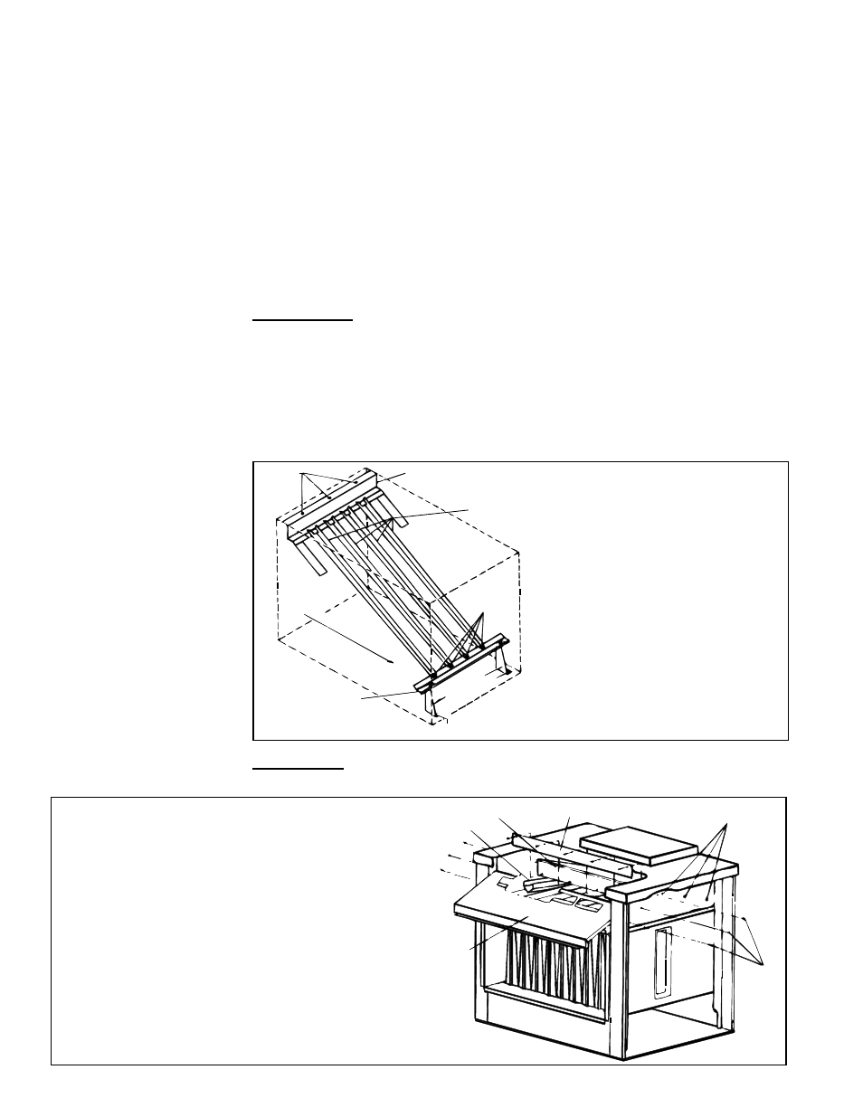
Instructions to Remove Heat Exchanger "V" Baf-
fles:
1) Remove the screws (the number varies depending
on unit size) along the bottom of the front baffle and
the three on each end Slide the front baffle out of
the furnace.
2) Remove the screws that attach the tube baffle hold-
down plate to the rear flue baffle.
3) Pull the "V" baffles out of the heat exchanger.
FIGURE 26 - Remove "V" Baffles to Clean
Inner Surface of Heat Exchanger Tubes
10.0 Maintenance
and Service
(cont'd)
Inner Surface - The inner surfaces (combustion air side) of the heat exchanger can
be reached for cleaning with the burner rack removed. (See Paragraph 10.2.3.) An