0 mechanical (cont'd), 3 duct furnace airflow (cont'd), 2 duct furnace blower connections – Reznor X Unit Installation Manual User Manual
Page 12
Form I-X, P/N 150491 R10, Page 12
Model X - Pressure Drop Table for 80% Thermal Efficient Duct Furnace
Size
75
100
125
150
175
200
225
250
300
350
400
Temp
Rise
CFM P.D. CFM P.D. CFM P.D. CFM P.D. CFM P.D. CFM P.D. CFM P.D. CFM P.D. CFM
P.D.
CFM P.D. CFM
P.D.
50°F
1105 0.2 1475 0.4 1840 0.5 2210 0.4 2580 0.5 2945 0.4 3315 0.5 3685 0.4
4420
0.6
5160
0.7
5895
0.7
60°F
920
0.2 1225 0.3 1535 0.3 1840 0.3 2150 0.4 2455 0.3 2765 0.4 3070 0.3
3685
0.4
4300
0.4
4915
0.5
70°F
790
0.1 1050 0.2 1315 0.3 1580 0.2 1840 0.3 2105 0.2 2370 0.3 2630 0.2
3160
0.3
3685
0.3
4210
0.3
80°F
690
0.1
920
0.2 1150 0.2 1380 0.2 1610 0.2 1840 0.2 2070 0.2 2300 0.2
2765
0.3
3225
0.3
3685
0.3
90°F
610
0.0
815
0.1 1020 0.2 1225 0.1 1430 0.2 1635 0.1 1840 0.2 2045 0.2
2455
0.2
2865
0.2
3275
0.2
The duct furnace must be installed on the positive pressure side of the field supplied
blower. The air throughput must be within the CFM range stated on the heater rating
plate. The air distribution must be even over the entire heat exchanger. Turning vanes
should be used in elbows or turns in the air inlet to ensure proper air distribution (See
Paragraph 6.3.2).
If it is determined that the blower CFM is greater than allowed or desirable, see Para-
graph 6.3.3 for instructions on determining the correct size of bypass duct required or
see the
APPENDIX, page 28, for instructions on converting the furnace for a higher
CFM application.
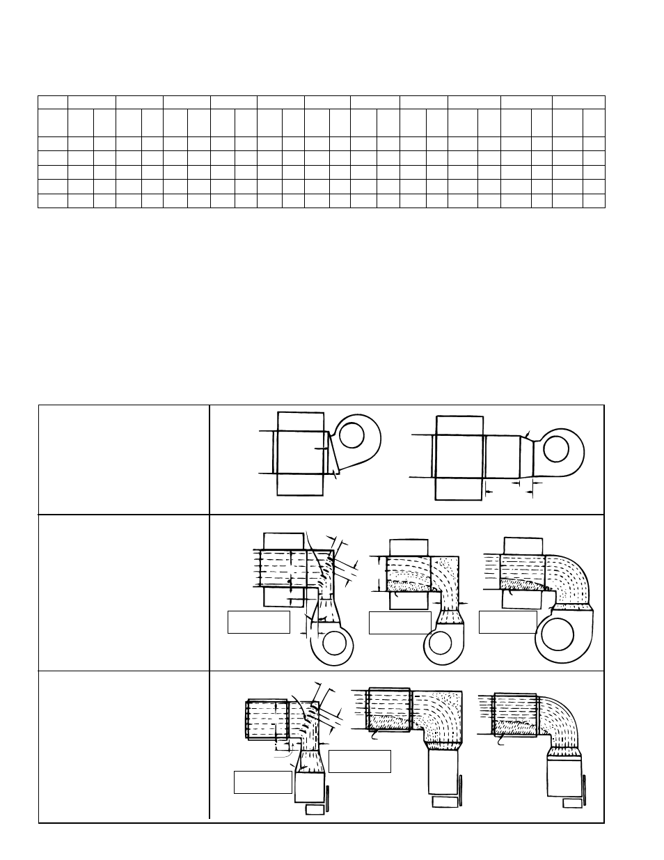
6.3.2 Duct Furnace
Blower Connections
6.0 Mechanical
(cont'd)
6.3 Duct Furnace Airflow (cont'd)
FIGURE 11A - Straight
Through Air Blower
Connection
FIGURE 11B - With Elbows
Up or Down
FIGURE 11C - With Elbows
Right or Left
Direct
Coupling
Slanted Transition
Suggested blower connections for straight through airflow.
Use either method for good air coverage and efficient operation.
15°
6 (152mm)
Remote
24
(610mm)
minimum
Turning Vanes
3(76mm)
3(76mm)
3(76mm)
6 (152mm)
6
(152mm)
X
15°
Y
No air
X
No air
Z
NOTE: X should
never be less than
1/2 Y
NOTE: X should
never be less
than 1/2 Y
NOTE: Angle Z
should never be
more than 15°
Turning Vanes
3(76mm)
3(76mm)
3(76mm)
6 (152mm)
6 (152mm)
Z
NOTE: Angle Z
should never be
more than 15°
X
15°
No air
GOOD
GOOD
POOR
POOR
POOR
No air
POOR
Y
Y
NOTE: X should
never be less
than 1/2 Y
6.3.1 Pressure Drop and Temperature Rise by Size (cont'd)
Proper arrangements of blower and duct furnace with respect to angle of approach of
the duct connection and the arrangement of the discharge opening of the blower are
shown in
FIGURES 11 A, B, and C. Blowers should be bottom horizontal discharge
when coupled to the duct furnace. If a top horizontal discharge blower is connected to
the duct furnace, be sure that sufficient length of duct is provided to permit even flow