5 pilot and ignition systems – Reznor X Unit Installation Manual User Manual
Page 21
Form I-X, P/N 150491 R10, Page 21
FIGURE 20B - Signal
Conditioner in Option
AG21
Computer Controlled Electronic Modulation between 50% and 100% Firing Rate
(Option AG21) - With this option the furnace is equipped with a Maxitrol signal condi-
tioner which operates much the same way as the amplifier above to control the regula-
tor valve. The conditioner accepts an input signal of either 4-20 milliamps or 0-10 volts
from a customer-supplied control device such as a computer. With the dip switches on
the conditioner in the "on" positions, the conditioner accepts a 4-20 milliamp signal. In
the "off" positions, the conditioner accepts a 0-10V signal. The conditioner converts the
signal to the 0 to 20 volt DC current required to control the modulating valve.
Spark Pilot
Flash Carryover
FIGURE 21 -
Burner Rack
with Spark
Pilot
Main Burner
8.5 Pilot and
Ignition
Systems
Model X furnaces have an intermittent spark pilot system. The horizontal pilot is located
in the control end of the burner rack and is accessible after the control compartment
panel has been removed. All pilots are target type with lint-free feature. Pilot gas pres-
sure should be the same as supply line pressure. (See Paragraph 6.1.) If required,
adjust the pilot flame length to approximately 1-1/4" with pilot adjustment screw in
control valve body.
Service NOTE: If your Model X heater was manufactured prior to 10/2003, it may have
a standing pilot. See wiring diagrams in the
APPENDIX, page 30.
Spark Ignition Safety Pilot System - Natural gas units are equipped with a spark
ignited intermittent safety pilot system that shuts off the pilot gas flow between heat
cycles. Propane units (or as an option on natural gas units) require a lockout device.
The lockout device stops the gas flow to the pilot if the pilot fails to light in 120 seconds.
The lockout feature has a one hour retry and requires manual set by interruption of the
thermostat circuit. Refer to the wiring diagram supplied with the unit for pilot system
identification and proper wiring. Pilot with lockout is Option AH3; spark pilot without
lockout is Option AH2.
Ignition Controller - As part of the intermittent safety pilot systems, the ignition con-
troller provides the high voltage spark to ignite the pilot gas and also acts as the flame
safety device. After ignition of the pilot gas, the ignition controller electronically senses
the pilot flame. A low voltage DC electrical signal is imposed on the separate metal
probe in the pilot assembly. The metal probe is electrically insulated from ground. The
pilot flame acts as a conduction path to ground completing the DC circuit and proving
pilot flame.
Proper operation of the electronic spark ignition system requires a
minimum flame signal of .2 microamps as measured by a microampmeter. With
pilot flame proven, the ignition controller energizes the main gas valve.
Service NOTE: If replacing an earlier style of ignition controller, order replacement
kit
P/N 257472 for a unit with recycling gas control Option AH2 or P/N 257473 for
Option AH3 gas control with lockout. (Option codes are listed on the unit wiring
diagram.)
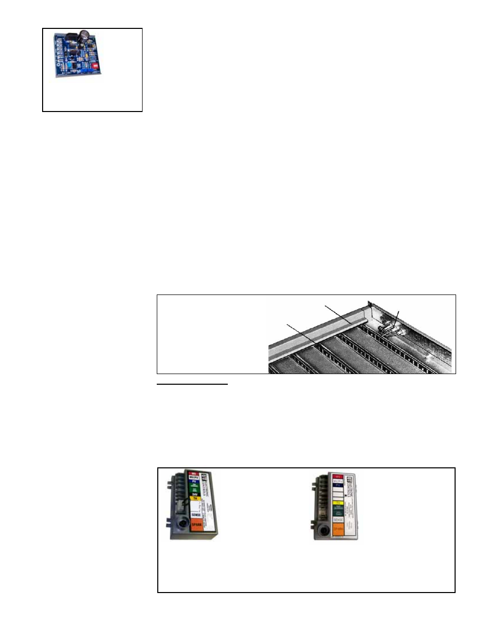
Use of an optional vent damper requires an ignition controller with lockout.
Ignition Controller
with Lockout,
UTEC 1003-514,
P/N 257010, for
Option AH3 Gas
Control
Recycling Ignition
Controller, UTEC
1003-638A, P/N
257009, for Option
AH2 Gas Control
FIGURE 22 - Ignition
Controllers