A) (b), 0 controls (cont'd), 4 gas controls (cont'd) – Reznor X Unit Installation Manual User Manual
Page 20
Form I-X, P/N 150491 R10, Page 20
Makeup air applications are usually adjusted to discharge an outlet air temperature
between 65°F and 75°F. In all applications, the allowable temperature rise of the fur-
nace in the installation dictates the limits of the ductstat temperature setting.
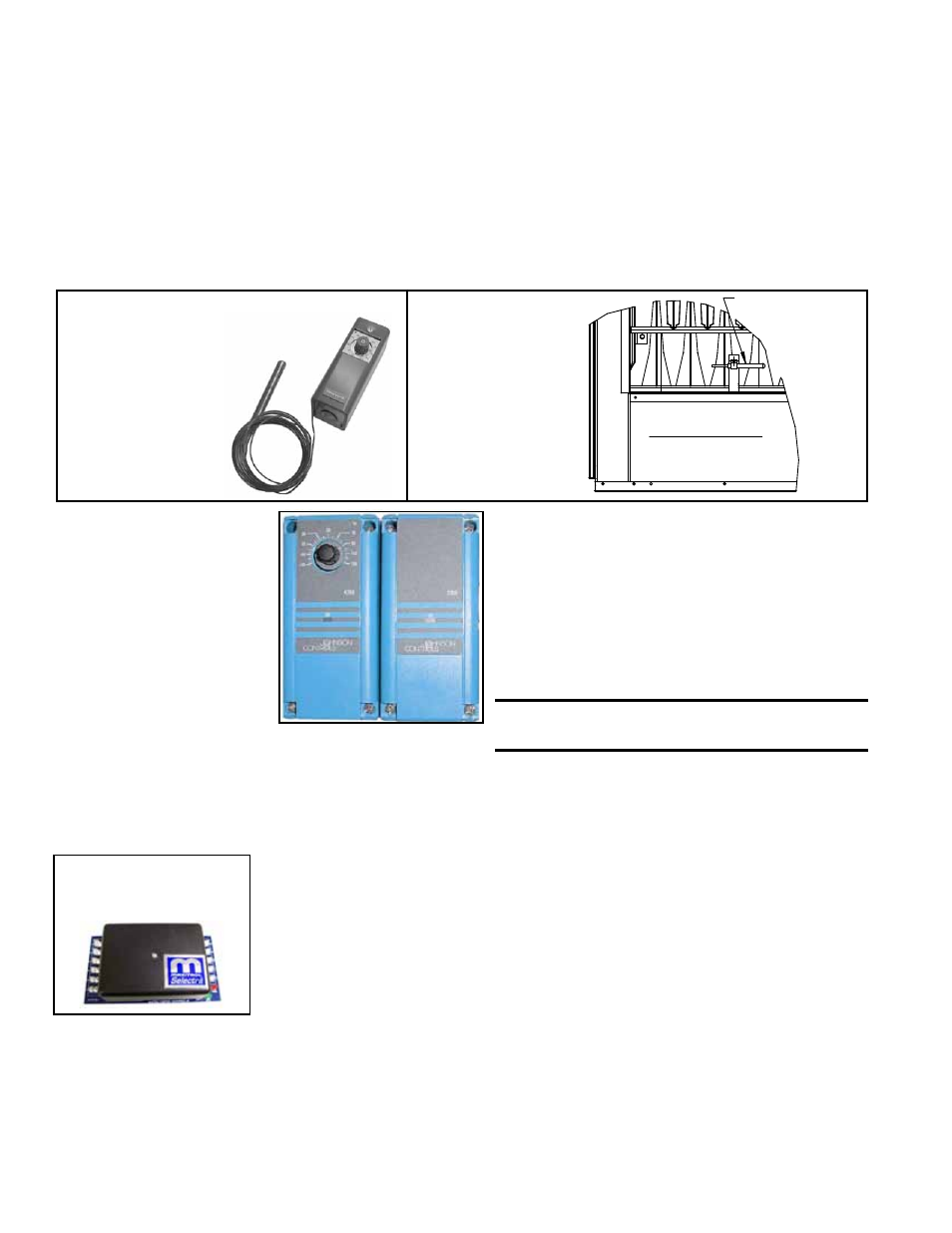
Depending on the option selection, the sensor is either connected by capillary tubing to
the unit-mounted ductstat (
FIGURES 18 and 19) or electrically connected to a remote
electronic temperature selector (
FIGURE 20). See Paragraph 6.3.5 for instructions on
locating the sensor in the ductwork.
Optional Ductstat with Capillary Tubing (FIGURE 18) - The control is set to 70°F
and has an adjustable range with a fixed differential of 2-1/2°F. Due to different CFM
settings and outside air temperatures, the average downstream outlet temperature
may not match the ductstat setting exactly. After the installation is complete, adjust the
setpoint of the ductstat to achieve the desired average discharge air temperature.
Adjustable range
0-100°F with a fixed
differential of 3°F.
FIGURE 18A - Ductstat
Control in Option AG3
FIGURE 18B -
Ductstat Bulb
Location (factory
installed)
Ductstat Bulb
in Option AG3
Model X Duct Furnace
Front (Discharge) View
FIGURE 19 - Ductstat
Control in Two-Stage
Makeup Air Control
Option AG15 -
(A) Remote
Temperature Selector;
(B) Stage-Adder
Module
(A)
(B)
Optional Ductstat with Electronic Remote Setpoint
Module (Option AG15) - The sensing probe is field-
wired to a remote temperature selector. The temper-
ature selector has an operating range to 120°F. The
remote modules are shipped separately for field instal-
lation.
Follow the wiring diagram with the unit and the manu-
facturer's instructions for wiring and installation.
There will be one module for selecting temperature and
one-stage adder module as illustrated in
FIGURE 20.
CAUTION: Be sure heat/cool selector
switch is set at "Heat" position.
8.4.4 Optional
Electronic Modulation
The type and capability of the electronic modulation system depends on the option
selected. Electronic modulation options are identified by a suffix to the Serial No.
printed on the heater rating plate. AG7 is identified as MV-1; AG8 is identified as MV-3;
AG9 is identified as MV-4; and AG21 is identified as MV-A.
Electronic Modulation between 50% and 100% Firing Rate (Options AG7, AG8,
AG9) - Depending on the heat requirements as established by the thermistor sensor,
the burner modulates between 100% and 50% firing. The thermistor is a resistor that
is temperature sensitive in that as the surrounding temperature changes, the Ohms
resistance changes through the thermistor. This change is monitored by the solid state
control center (amplifier) which furnishes varying DC current to the modulating valve to
adjust the gas input.
Each modulating valve is basically a regulator with electrical means of raising and
lowering the discharge pressure. When no DC current is fed to this device, it functions
as a gas pressure regulator, supplying 3.5" w.c. pressure to the main operating valve.
Refer to the wiring diagram supplied with the furnace for proper wiring connections. Elec-
tronic modulation for heating controlled by a specially designed room thermostat (60°-
85°F) is identified as Option AG7. Electronic modulation control systems for makeup
air applications controlled by a field-installed duct sensor (See Paragraph 6.3.5.) and
temperature selector (55-90°F) are identified as either Option AG8 or Option AG9.
The temperature selector setting for Option AG8 is on the amplifier; Option AG9 has a
remote temperature selector. Both systems are available with an override thermostat.
8.0 Controls
(cont'd)
8.4 Gas Controls
(cont'd)
8.4.3 Optional Two-
Stage Operation for
Makeup Air (cont'd)
Factory
set at
70°F
FIGURE 20A -
Amplifier in Options
AG7, AG8, and AG9