2 maintenance procedures – Reznor X Unit Installation Manual User Manual
Page 25
Form I-X, P/N 150491 R10, Page 25
10.2.1 Operating Gas Valve
WARNING
The operating valve is the prime safety shutoff. All gas supply lines
must be free of dirt or scale before connecting to the unit to ensure
positive closure. See Hazard Levels, page 2.
Remove external dirt accumulation and check wiring connections.
The combination gas valve must be checked annually to ensure that the valve is shut-
ting off gas flow completely.
Instructions:
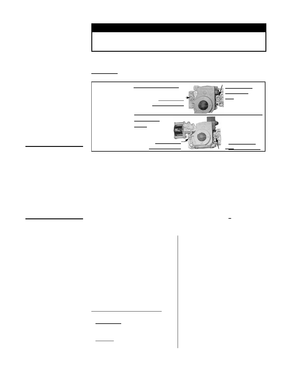
1) Locate the 1/8” FPT INLET pressure tap on the combination valve (FIGURE 24).
Single-Stage Valve
Two-Stage
Valve
1/8" INLET
Pressure Tap
1/8” Outlet
Pressure
Tap
1/8" INLET
Pressure Tap
1/8” Outlet
Pressure Tap
FIGURE 24 -
Gas Valve
Shutoff
Check
10.2.2 Burner Rack
Removal Instructions
2) With the manual valve turned off to prevent flow to the gas valve, connect a
manometer to the 1/8” inlet pressure tap in the valve.
NOTE: A manometer (fluid-
filled gauge) with an inches water column scale is recommended.
3) With the field-installed manual valve remaining closed, observe the manometer for
two to three minutes for an indication of gas pressure. No pressure should be indi-
cated on the manometer.
If the manometer indicates a gas pressure, the field-installed manual gas valve
must be replaced or repaired before the combination gas valve can be checked.
4) If the manometer does not indicate gas pressure, slowly open the field-installed
manual gas valve. After the manometer's indicated gas pressure has reached
equilibrium, close the manual shutoff valve. Observe the gas pressure. There
should be no loss of gas pressure on the manometer. If the manometer indicates
a loss of pressure, replace the combination gas valve before placing the heater in
operation.
CAUTION: DO NOT
bottom out the gas
valve regulator
adjusting screw.
This can result
in unregulated
manifold pressure
causing excess
overfire and heat
exchanger failure.
NOTE: Operational
pressure settings and
instructions for checking
pressure settings are in
Paragraph 6.1.
10.2 Maintenance
Procedures
1. Turn off the gas supply.
2. Turn off the electric supply.
3. Remove control access side panel.
4. Disconnect the pilot tubing &
thermocouple or flame sensor lead.
5. Mark and disconnect electric valve
leads.
6. Uncouple the union in the gas supply.
7. Remove sheetmetal screws in the top
corners of the burner rack assembly.
8. Pull "drawer-type" burner rack out of
the furnace.
To disassemble the burner rack:
1. Remove Carryover System --
Natural Gas - remove the flash
carryover system from the "manifold
end" of the burner rack.
Propane - break the lighter tube
connection at the regulator and remove
the lighter tube orifice supply tubing;
remove the retaining screws in the
drip shield and the shield; remove
the retaining screws and slide out the
lighter tube.
2. Pull main burners horizontally away
from injection opening and lift out.
3. Remove manifold bracket screws and
remove manifold.
4. Remove main burner orifices.
5. Remove screws and lift out pilot
burner.
Follow the instructions in Paragraph
10.2.3 to clean. To re-assemble and
replace, reverse the above procedures
being careful not to create any unsafe
conditions.