0 mechanical, 1 gas piping and pressures, Figure 7 - gas supply connection – Reznor RDF Unit Installation Manual User Manual
Page 9
I-RDF, PN148384R5, Page 9
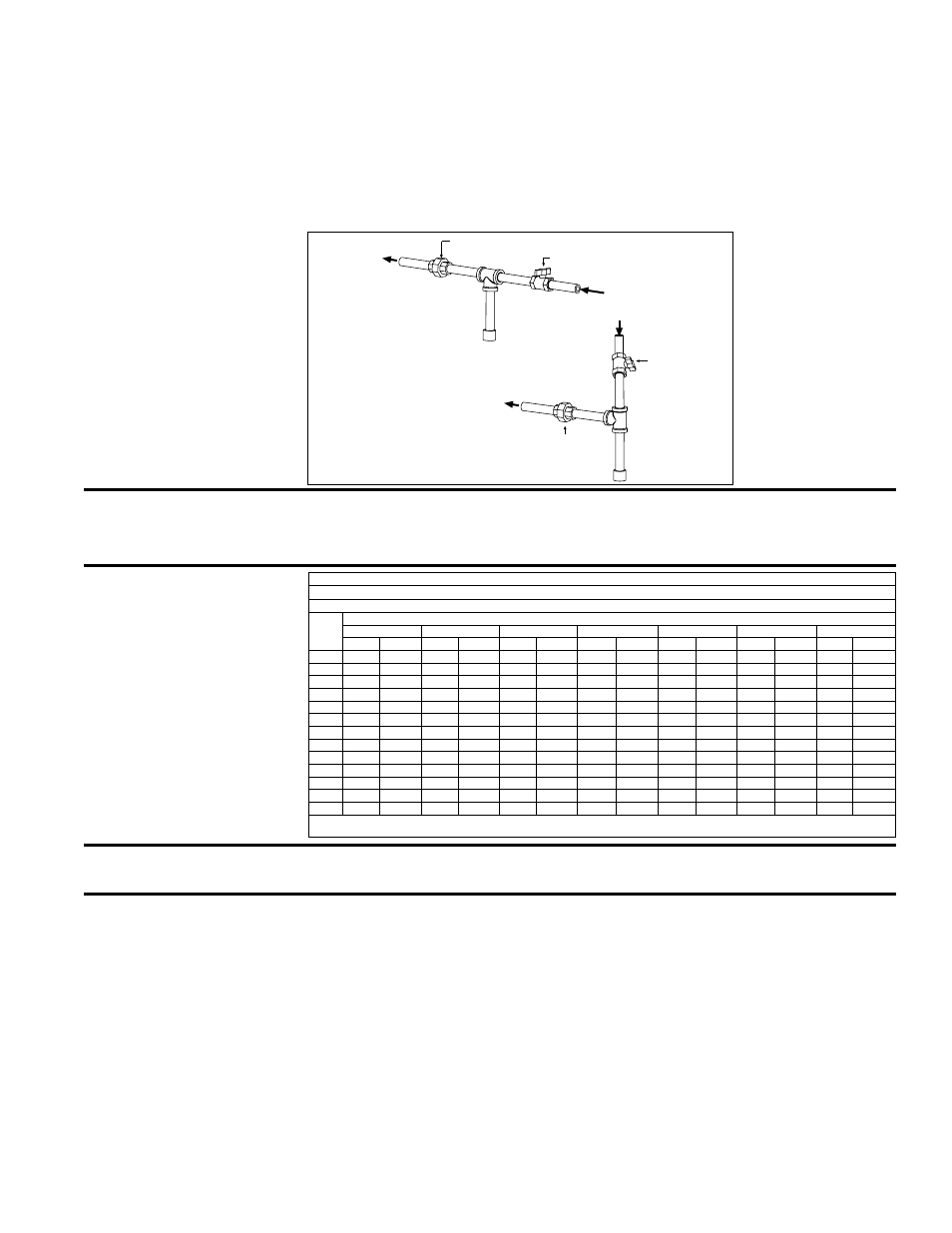
6.1 Gas Piping and Pressures
All piping must be in accordance with the requirements of the National Fuel Gas Code
ANSI/Z223.1 (latest edition) or CSA B149.1 and B149.2. Gas supply piping installa-
tion must conform with good practice and with all local codes. Read this section of the
installation manual to determine the minimum gas supply pressure required to provide
a maximum gas capacity. Minimum gas supply pressure is also stated on the heater
rating plate. The heater manifold terminates at the gas supply connection with a black
iron pipe union. See
FIGURE 7. Local codes may require a 6" condensate trap. Gas
connection is either 1", 1-1/4", or 2" depending on the size of the system.
WARNING: High pressure testing of supply lines is acceptable, provided the supply
line has been disconnected from the unit and the pipe end is capped. See Hazard
Levels, page 2.
FIGURE 7 - Gas
Supply Connection
6.0 Mechanical
From Gas Supply
(horizontal or vertical)
Manual
shutoff
Drip
Leg
*To Gas
Valve
(inside the
cabinet)
*To Gas
Valve
(inside the
cabinet)
Ground
Joint
Union
Drip
Leg
Ground Joint Union
Manual shutoff
Capacity of Piping - Cubic Feet per Hour based on 0.3" w.c. Pressure Drop
Specific Gravity for Natural Gas -- 0.6 (Natural Gas -- 1000 BTU/Cubic Ft)
Specific Gravity for Propane Gas -- 1.6 (Propane Gas -- 2550 BTU/Cubic Ft)
Length
of Pipe
Diameter of Pipe
1"
1-1/4"
1-1/2"
2"
2-1/2"
3"
4"
Natural Propane Natural Propane Natural Propane Natural Propane Natural Propane Natural Propane Natural Propane
20'
350
214
730
445
1100
671
2100
1281
3300
2013
5900
3599
12000
7320
30'
285
174
590
360
890
543
1650
1007
2700
1647
4700
2867
9700
5917
40'
245
149
500
305
760
464
1450
885
2300
1403
4100
2501
8300
5063
50'
215
131
440
268
670
409
1270
775
2000
1220
3600
2196
7400
4514
60'
195
119
400
244
610
372
1105
674
1850
1129
3250
1983
6800
4148
70'
180
110
370
226
560
342
1050
641
1700
1037
3000
1830
6200
3782
80'
170
104
350
214
530
323
990
604
1600
976
2800
1708
5800
3538
90'
160
98
320
195
490
299
930
567
1500
915
2600
1586
5400
3294
100'
150
92
305
186
460
281
870
531
1400
854
2500
1525
5100
3111
125'
130
79
275
168
410
250
780
476
1250
763
2200
1342
4500
2745
150'
120
73
250
153
380
232
710
433
1130
689
2000
1220
4100
2501
175'
110
67
225
137
350
214
650
397
1050
641
1850
1129
3800
2318
200'
100
61
210
128
320
195
610
372
980
598
1700
1037
3500
2135
Note: When sizing supply lines, consider possibilities of future expansion and increased requirements. Refer to National Fuel Gas Code for additional
information on line sizing.
Gas Supply Piping
Supply Pressure
Requirement by
Manifold Option
These direct-fired makeup air systems are designed to operate on a natural gas sup-
ply differential pressure range of a minimum of 4.3-5.0" w.c. plus the manifold pres-
sure drop. Maximum supply pressure depends on specific unit firing rate and manifold
selection. If the natural gas supply pressure is above the maximum allowed, it is nec-
essary to install a field-supplied step-down gas regulator in the supply line. Order and
install the appropriate Gas Regulator Kit, Option CZ1 (1") or CZ2 (1-1/2"). These kits
include spring-loaded, lockup type regulators that comply with national and local codes
specifying that type of regulator. Follow the instructions provided with the kit. Measure
the gas pressure between the step-down regulator and the unit.
WARNING: All components of the gas supply system must be leak tested prior to
placing equipment in service. NEVER TEST FOR LEAKS WITH AN OPEN FLAME.
Maximum Supply Pressure by Manifold
Manifold Option BM75, BM76, BM77 - 1/2 psi
Manifold Option BM78, BM79 - 2 psi
Manifold Option BM80, BM81 - 5 psi