Supports, 4 mounting on a roof curb, 0 mounting (cont'd) – Reznor RDF Unit Installation Manual User Manual
Page 6: 3 mounting on field-supplied supports 5.1 weights, 2 rigging
I-RDF, PN148384R5, Page 6
5.3 Mounting on
Field-Supplied
Supports
5.1 Weights
NOTE: Net weights are approximate for the standard system. Optional equipment is
not included.
Net Weight of Basic Model RDF System
Sizes
1-20
1-40
1-50
1-65
2-80
2-120
3-180
3-260
lbs
915
925
935
950
1455
1505
2410
2480
kg
415
420
424
431
670
683
1093
1125
5.2 Rigging
All units are mounted on a full curb cap base furnished with four lifting lugs for attaching
rigging. To prevent damage to the cabinet, use spreader bars with the rigging chains.
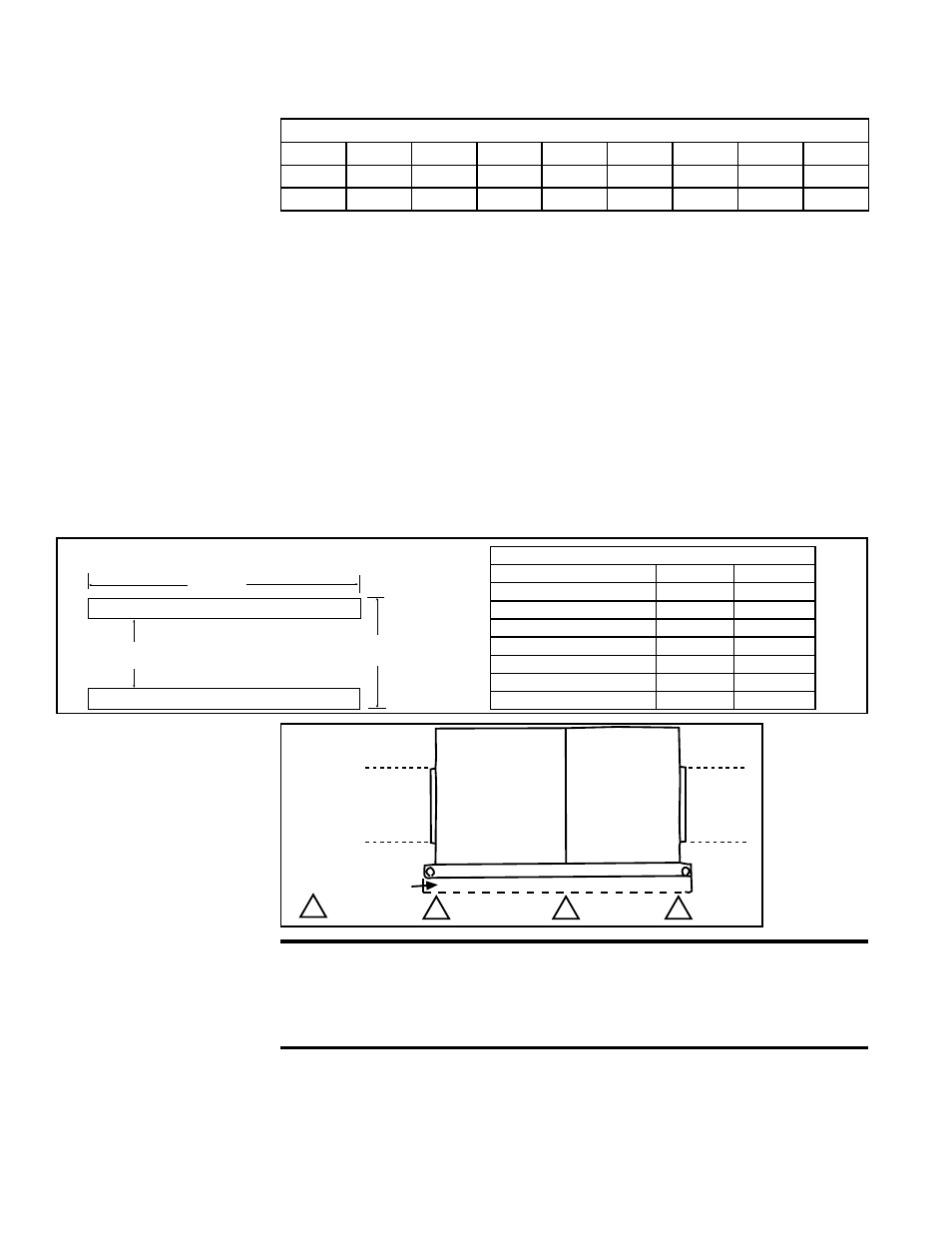
FIGURE 2 - Placement of Mounting Rails
A
B
4 x 4 Treated Lumber
FIGURE 3 - Cross
Support Mounting
Requirements
Field
Supplied
Duct
Field
Supplied
Duct
4 x 4 Treated Lumber
= support location
Mounting Rail Placement
Model
A (inches) B (inches)
1-20, 1-40, 1-50, 1-65
85-1/4
45-1/2
2-80, 2-120
85-1/4
69-7/16
3-180, 3-260
132-5/8
83-1/16
Model
A (mm)
B (mm)
1-20, 1-40, 1-50, 1-65
2165
1156
2-80, 2-120
2165
1764
3-180, 3-260
3369
2110
5.4 Mounting on a
Roof Curb
CAUTION: Before installing curb, recheck to be sure that the
correct curb has been ordered. Be sure that the curb selected
matches the unit ordered. Verify the dimensions of the curb
received with the dimension table in FIGURE 4.
Roof Curb
Dimensions for Model
RDF Series 3
Whether the roof curb is Option CJ3 designed for the system or a field-supplied curb,
the roof curb dimensions in
FIGURE 4 and the ductwork opening dimensions in FIG-
URE 6 apply.
The roof curb designed for the system includes dividers that will create internal duct-
work and duct connection flanges for ease of installation and so that the building duc-
twork can be attached before the system is set on the roof curb.
The system is equipped with a load-bearing curb cap which forms an integral part of
the unit. The curb cap provides required clearance from combustibles. Whether the
system is being mounted directly on a surface or being placed "up" on additional struc-
ture, the horizontal length must be supported by two 4x4 treated wooden rails. Refer
to
FIGURE 2 for the appropriate lengths and spacing. When the system is placed on
the rails, the curb cap "skirt" must fit over the edge of the boards with the rails setting
inside the horizontal length of the curb cap.
If the rails are laid directly on the mounting surface, position them as shown in
FIGURE
3. Set the system on the rails leaving the "ends" underneath open for ventilation.
If the wooden rails are not placed directly on a surface, cross-supports should be
placed underneath the rails at the ends and at the cabinet "joint". Refer to
FIGURE 3.
IMPORTANT NOTE: Mount an outdoor unit with a minimum of 14" clearance from the
bottom of the inlet air hood to the mounting surface.
5.0 Mounting
(cont'd)