0 electrical supply and wiring – Reznor RDF Unit Installation Manual User Manual
Page 17
I-RDF, PN148384R5, Page 17
7.0 Electrical
Supply and
Wiring
All electrical wiring and connections including electrical grounding must be in accor-
dance with the National Electric Code ANSI/NFPA No. 70 (latest edition) or the Cana-
dian Electrical Code Part 1-C.S.A. Standard C22.1. Check any local ordinances or
utility company requirements that apply.
Run a separate line voltage supply directly from the building electrical panel to the dis-
connect switch for the system. All external wiring must be within approved conduit and
have a minimum temperature rise rating of 60°C. For motor load amps, see Paragraph
6.4 or check the motor nameplate. System FLA is on the rating plate.
Specific wiring diagrams and complete instructions are packed with each unit and
should be kept readily accessible in legible condition.
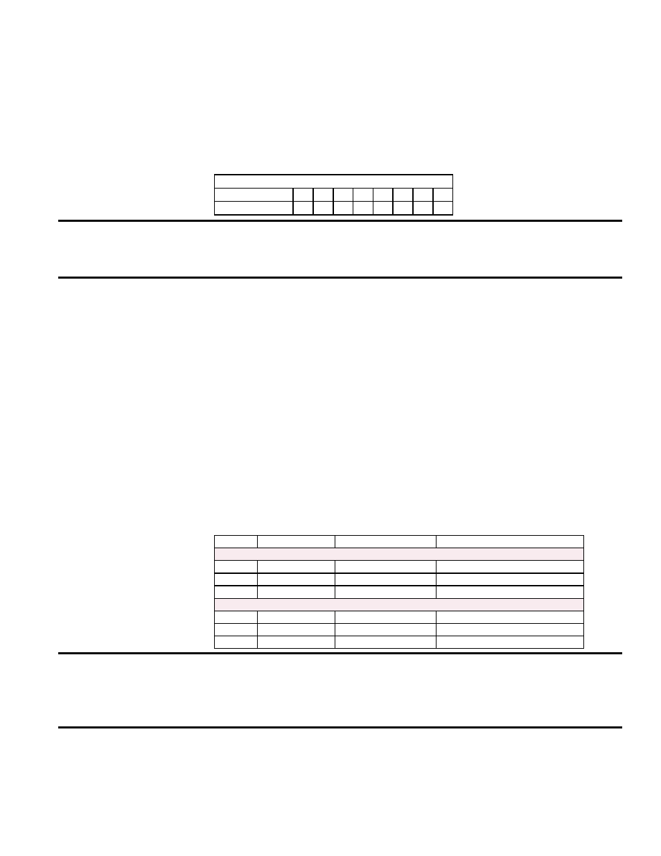
Wire Gauge - 100 ft (30M) maximum
Full Load Amps 5 10 15 20 25 30 35 40
Wire Gauge
14 14 12 10 8 8 6 6
Convenience Outlet
Option
CAUTION: If any of the original wire in the unit must be replaced, the replacement
wire must have a temperature rating of at least 105°C except for controls mounted in
the discharge airstream which must be 150°C. See Hazard Levels, page 2.
When a convenience outlet option is included, an individual power supply must be
provided to the receptacle. This circuit MUST BE on a ground fault breaker to meet
requirements. All wiring to the convenience outlet must meet National Electrical Code
ANSI/NFPA No. 70 (latest edition) or the Canadian Electrical Code Part 1-C.S.A. Stan-
dard C22.1. and any local or utility codes that may apply.
Disconnect Switch
A safety disconnect is required. Refer to
FIGURE 14 for recommended location and
install the disconnect switch in accordance with Article 430 of the National Electrical
Code ANSI/NFPA 70 or in accordance with Canadian Electrical Code Part 1-C.S.A.
Standard C22.1. When attaching the disconnect switch to the heater, use hardware
with "teeth" to provide electrical grounding. The "teeth" should face the disconnect
switch, scratching off the painted surface. Attach the disconnect tightly against the
heater cabinet. Run cable so that it does not interfere with cabinet panels or doors.
When providing or replacing fuses in a fusible disconnect switch, use dual element
time delay fuses and size according to 1.25 times the maximum total input amps.
Control Wiring
A 7/8" diameter opening suitable for watertight conduit connection is provided as the
entrance of 24-volt control wiring to the electrical compartment. For location, see
FIG-
URE 14, page 18. Low voltage wiring must be in individual conduit, separated from
primary high voltage wiring.
Volts
Wire Gauge
Total Wire Length
Distance from Unit to Control
Control Wiring Maximum Lengths (ft)
24
18
150
75
24
16
250
125
24
14
350
175
Control Wiring Maximum Lengths (M)
24
18
45.7
22.9
24
16
76.2
38.1
24
14
106.7
53.3
CAUTION: Supply voltage and 24-volt control wiring cannot be installed in the same
conduit. Maxitrol systems will be adversely affected if control wiring is in conduit
with supply voltage wiring. If required, field-supplied wiring between any Maxitrol
components must be completed with shielded wiring.
A 3-position control switch mounted in a 4x4 box is supplied with each system (excep-
tion - not included with systems with Option AG37 designed for computer control),
either packed loose inside the unit, or if an optional control console (Option RC13 or
RC14; See
FIGURE 15) is ordered, the switch is mounted on the console.
Control wiring requirements depend on the options selected. Follow the custom wiring
diagram supplied with the system to connect any remote controls. In this paragraph,