0 mechanical (cont'd), 2 unit inlet air (cont'd) – Reznor RDF Unit Installation Manual User Manual
Page 12
I-RDF, PN148384R5, Page 12
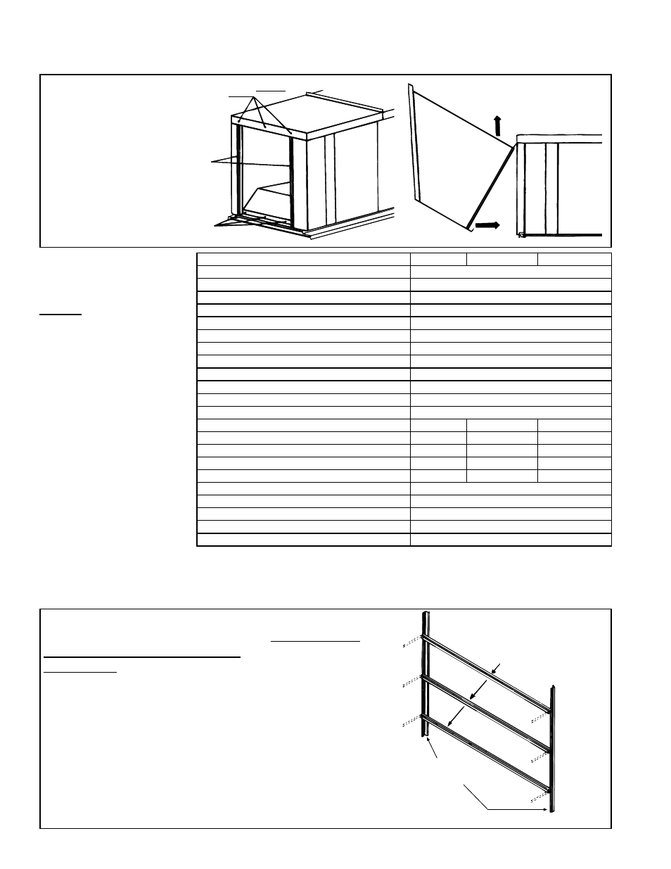
6.0 Mechanical
(cont'd)
STEP
2
STEP 3
Remove
sheetmetal
screws
Slip
Groove
Remove
sheetmetal
screws
STEP 1
Outside
Air Hood
or Filter
Cabinet
Assembly and
Installation
Instructions for
ITEM 2 in the Table
on page 11 - Refer to
FIGURES 11A-11N.
Option AS2, Outdoor
Screened Air Hood without
Filters -
Pkg P/N 71150
Option AS6, Outdoor
Screened Air Hood with 1"
Filters -
Pkg P/N 71152
Option AS7, Outdoor
Screened Air Hood with 2"
Filters -
Pkg P/N 72627
FIGURE 10 -
Attach factory
-assembled
Cabinet or
Hood
Option Components (qty in parenthesis)
AS2
AS6
AS7
Top of Inlet Hood Cabinet Section
(1)
91575
Top of Inlet Hood
(1)
91576
Clamp for Top Seam (Hood to Cabinet)
(1)
91577
Bottom of Hood Cabinet Section
(1)
91567
Supports (2 pieces per leg)
(6)
91581
Left Side of Hood
(1)
91568
Right Side of Hood
(1)
91569
Intermediate Posts - Cabinet Section
(2)
91578
Rt/Lft Corner Post - Cabinet Section
(2)
91579
Doors (Filter Access on AS6 and AS7)
(2)
91585
Center Louver Top/Bottom Supports
(2)
91582
Factory-assembled Louver Sections w/Screen
(2)
113003
Top and Bottom Filter Channels
N/A
(2)
91580
(2)
94224
Pre-assembled Center Filter Channels
N/A
(5)
91586
(5)
94223
Top/Btm Filter Block Off Plate
N/A
(2)
91584
(2)
98764
Filter Block Off Sections
N/A
(6)
95335
(6)
96335
Permanent Filters
N/A
(12) 1",
87251 (10) 2", 94383
Sheetmetal Screws #10 x 1/2" long
(100)
11813
Screws 1/4-20 x 5/8" long (bolt type)
(15)
10393
Hex Nuts 1/4-20 (Keps)
(15)
7328
Sheetmetal Screws #14-110 x 3/4" long
(3)
41463
J Type Clip-On Nut
(5)
1849
1. S
creened Air Inlet Hoods with Filters (Options AS6 and AS7 for Sizes 3-180, 3-260) - Build filter racks and cabi-
net section;
follow all Steps.
Screened Air Inlet Hood without Filters (Option AS2 for Sizes 3-180, 3-260) - Build cabinet section; skip Steps
1A, 1B, and 1C.
Start with Step 1D ignoring filter rack illustrations.
Step 1A - Assemble Inner Side of Filter Rack
(Applies to Options AS6 and AS7 only; for Option AS2
without filters, proceed to Step 1D)
Parts Required -- Right corner post, left corner post, three of the
five pre-assembled center filter channels, and twelve 1/2" long
screws
Corner posts come with two sets of holes.
For 1" filters (Option AS6), attach the three filter channel
assemblies using the holes in the corner posts closest to the
inside.
For 2" filters (Option AS7), attach the three filter channel
assemblies using the holes in the corner posts closest to the
outside edge.
Pre-assembled Center Filter Channels
(NOTE: There are five center filter
channels. The other two are used
on the other side of the
filter rack in Step 1C.)
P/N 91579
Corner Post
6.2.1 Outside Air Hood or Indoor Filter Cabinet (cont'd)
6.2 Unit Inlet Air (cont'd)
FIGURE 11A