1 clearances, 0 general (cont'd), 0 location – Reznor RDF Unit Installation Manual User Manual
Page 4: 0 uncrating/ preparation, 0 clearances and dimensions, 4 installation codes/requirements (cont'd)
I-RDF, PN148384R5, Page 4
Codes for Special Installations: (1) Aircraft Hangar -- Installation in an aircraft han-
gar must be in accordance with the Standard for Aircraft Hangars, ANSI/NFPA 409 (lat-
est edition) or CAN/CGA B149 Installation Codes; (2) Public Garage -- Installation in a
public garage must be in accordance with the Standard for Parking Structures, ANSI/
NFPA 88A (latest edition) or the Standard for Repair Garages, ANSI/NFPA 88B (latest
edition) or in Canada with CAN/CGA B149 Installation Codes.
1.0 General
(cont'd)
1.4 Installation Codes/Requirements (cont'd)
2.0 Location
Location must comply with clearances in Paragraph 4.1. Makeup air should enter at
the highest point practical. By doing this, the fresh air will entrain dust laden air at the
ceiling and move it toward the point of exhaust. Also, fresh air directed downward from
the roof or ceiling will mix with hot ceiling air resulting in improved distribution of heat
in the building.
Always introduce fresh makeup air so that it moves across the greatest distance within
the room or building before reaching an exhauster.
3.0 Uncrating/
Preparation
Immediately upon uncrating the unit, check the gas specifications and electrical volt-
age (system rating plate is in the control compartment) to be sure that they agree with
the supply at the installation site. Check for any damage that may have been incurred
during shipment. If damage is found, document the damage with the carrier and con-
tact your distributor.
The following control parts are
shipped loose inside the unit:
• a 3-position control switch mounted in a 4x4 junction box (except units with Option
AG37) NOTE: If an optional remote console is ordered, this switch is mounted on
the console; the console is shipped separately.
Depending on the gas and/or air controls selected, the following additional parts are
shipped inside the unit or separately.
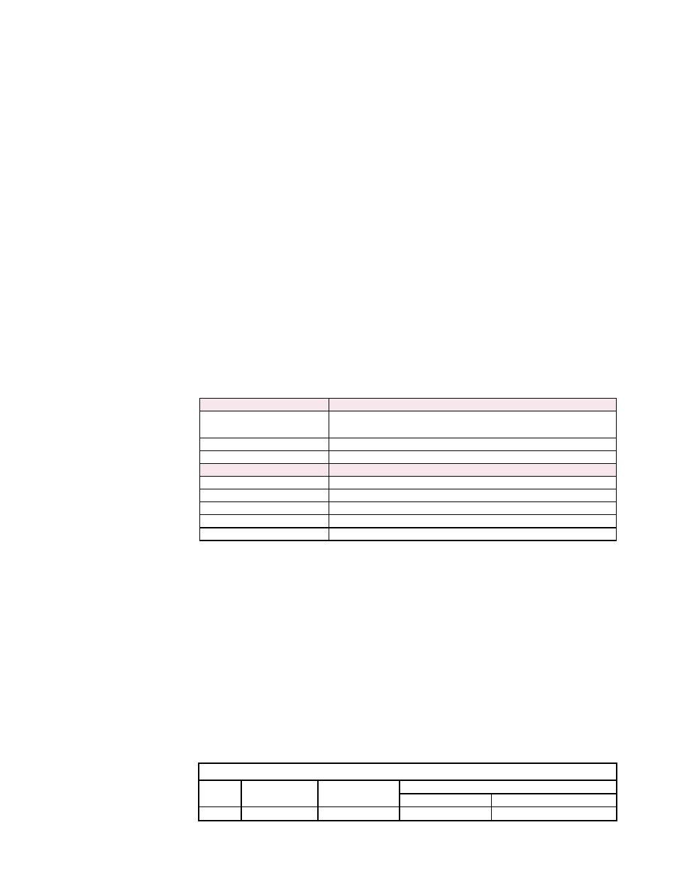
Gas Controls
Shipped-Loose Parts
Options AG30, AG32, AG33,
AG47, AG48
*Remote Temperature Selector
Option AG31
*Remote Temperature Selector, Space Override Thermostat
Option AG36
Remote Console
Air Controls
Shipped-Loose Parts
Option AR19, AR22
*Potentiometer
Option AR20, AR23
Remote Pressure Sensor
Option AR32
Toggle Switch
Option AR36
Photohelic Pressure Sensor
Option AR37
Photohelic Pressure Sensor
*If an optional remote console is ordered, these controls are mounted on the console.
The console is shipped separately.
On all sizes with an
optional dirty filter switch, the tubing and clamps are shipped
inside the cabinet.
Be sure that all shipped-separate accessories for the installation are available. Other
shipped-separate accessories could include a roof curb, a remote console, an outside
air hood, a disconnect switch, and/or an indoor filter cabinet.
4.0 Clearances
and
Dimensions
4.1 Clearances
Clearances - inches (mm)
Top
Control Side Side Opposite
Controls
Bottom
To Combustibles
To Non-Combustibles
3 (76) Width of unit
3 (76)
3 (76)
0 - Curb
Clearance to combustibles is defined as the minimum distance from the heater to a
surface or object that is necessary to ensure that a surface temperature of 90°F above
the surrounding ambient temperature is not exceeded. In order to service the system,
the minimum clearance on the control side of the unit must be equal to the width of the
unit.