0 check-test start, Before startup, Key to check/test/ startup procedures – Reznor RDF Unit Installation Manual User Manual
Page 22: Procedure applies to all units
I-RDF, PN148384R5, Page 22
9.0 Check-Test
Start
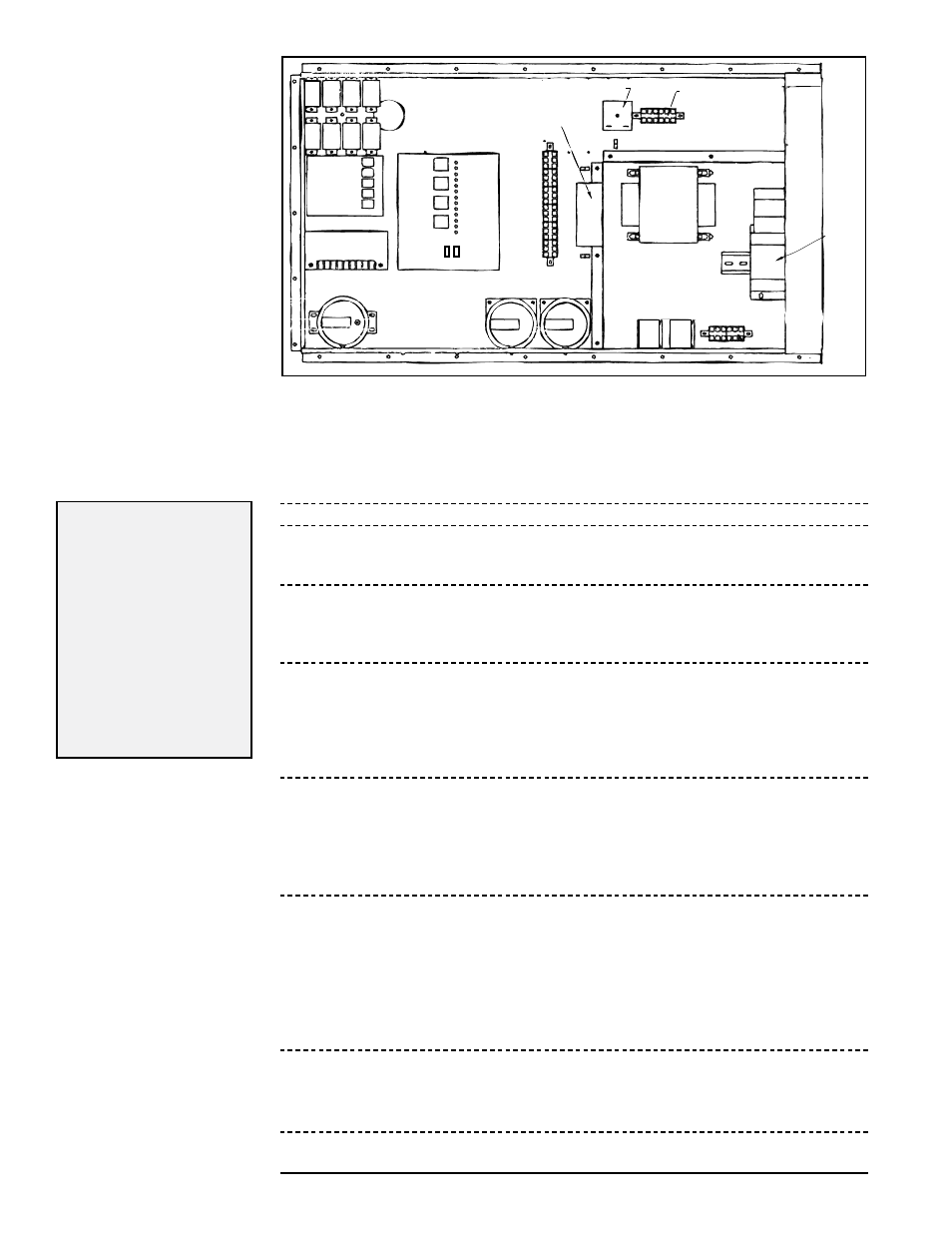
FIGURE 28 -
Control Locations
in the Electrical
Compartment
(NOTE: Locations may not
be identical, but controls
should be similar.).
Control Relays
Outside Air Cutoff
(high ambient limit control)
Time Delay Relay
24-volt Terminals
Ignition
Module
Maxitrol Amplifier
or Signal
Conditioner
Service
Switches
St
atus Light
s
Circuit
Board
24-V
olt T
erminals
Motor
Starter
Transformer
Line Voltage
Terminals
St
arter
Relay
Relay for
Optional
2-Speed
High
Low
Standard Pressure
Switches
Optional Dirty Filter
Pressure Switch
IMPORTANT NOTE: These instructions are designed for systems manufactured beginning 8/2003 equipped with hot
surface ignition and standard diagnostic lights. If the system being started was manufactured prior to 8/2003, contact
your representative or the factory service department for appropriate startup procedures.
Check/Test/Startup
Procedures (Follow
Steps in Sequence)
Before Startup
1. Check to be sure that all field-installed accessories are installed.
2. Check all field-installed wiring.
3. Check all ductwork for obstructions; open all diffusers.
4. Turn the three-position switch or optional summer/off/winter remote console
switch to OFF position. To prevent someone from turning the system on, tape the
switch leaving a note that it should be left in the OFF position.
5. If the system includes an air control with a remote potentiometer, set the posi-
tion as follows::
Option AR19 (Variable Air Volume) - Turn full "open"
Option AR22 (Return Air) - Turn full "closed"
6. Check disconnect switch --
Turn disconnect switch OFF.
Check disconnect switch to be sure that it is tightly secured against the cabinet.
If disconnect is fusible, check that fuses are installed. If fuses are not installed,
insert dual element time delay fuses sized 1.25 times the maximum total input
amps. Verify continuity of fuses.
7. Open the hinged gas/electric control compartment door --
Close all manual gas valves.
Check all wiring and wiring connections on gas controls and electrical components.
If equipped with any manually reset devices such as an optional firestat limit switch,
a high limit switch, and/or optional high gas pressure switch, reset devices. Check
setpoint on the high ambient burner cutoff air control (60°F).
8. Open the hinged door to the blower compartment --
Remove any blocking and shipping supports.
Check that the blower belts are installed and have correct tension and that pulleys
are in alignment and locked to the shaft (See Paragraph 6.4).
Inside the compartment, remove the cover from the limit switch junction box.
Reset manual limit switch.
Check wiring connections to limit switches, discharge air sensor, and motor.
Replace the junction box cover.
9. Turn ON gas supply valve and inlet manual shutoff valve on the manifold.
Leak test gas connections upstream of the electric gas valve. Be sure all connec-
tions are tight and leak tested.
WARNING: DO NOT TEST WITH OPEN FLAME.
Turn OFF manual gas valves.
10. Turn blower service switch (Electrical Compartment, See FIGURE 28) to OFF
position. If present, verify that damper test switch is in TEST position.
KEY to Check/Test/
Startup Procedures:
Procedure
applies to all
units.
Procedure only
applies to units
with the optional
component
referred to in
that procedure.