0 check-test start (cont'd), Startup (cont'd) – Reznor RDF Unit Installation Manual User Manual
Page 24
I-RDF, PN148384R5, Page 24
9.0 Check-Test
Start (cont'd)
Startup (cont'd)
Turn on the disconnect switch and re-check the slope gauge. If air pressure differ-
ential is within the limits of -.25" to -.75" w.c., no further adjustment is required. If
the air pressure differential is not within those limits, re-adjust the blower speed.
When the differential air pressure is within the limits, check the motor amp draw
with an ammeter to be sure that the motor is not overloaded. Amps are shown on
the motor nameplate.
If an inlet or outlet duct system is attached to the heater, run the blower to purge
the volume of air from the duct system with at least four air changes.
Turn the blower switch to OFF and damper test switch to RUN. Turn the disconnect
switch OFF. Disconnect the manometer and the slope gauge. Replace the caps.
Observe for ignition through the viewport.
Check for lights - Lights listed in prior Steps should be energized. After 15-20
seconds, the
"Pilot Valve" light will light to signal the pilot ignition, followed by the
"Main Valve" light signaling main burner operation.
With both the burner and blower operating, measure the gas pressure at the
burner. Gas pressure should match the required manifold pressure listed on the
rating plate. (If pressure does not match the required pressure, further testing is
required in Step 5.) Remove the manometer.
Leak test all connections in the pilot and main burner supply lines.
WARNING: DO
NOT TEST WITH OPEN FLAME.
Check output of pilot flame signal. Microampmeter reading should be .5 or greater.
To check lockout feature of the pilot ignition system, turn pilot manual shutoff valve
OFF. Pilot should lockout after two trials for ignition. To reset unit, open the valve
and cycle the main disconnect switch.
Turn OFF the manual gas valve. Wait 30 seconds for unit to cool. Return both
burner and blower switch to OFF position. Turn OFF disconnect switch.
4. Check pilot pressure --
To check pilot gas pressure, connect a "U"-tube manometer to the pressure tap on
the downstream side of the pilot solenoid valve.
Put BOTH the blower and burner switch in TEST position. Turn ON disconnect
switch. Blower should be energized.
Measure pilot gas pressure. Pilot pressure for natural gas should be 3.5" w.c.; pilot
pressure for propane gas should be 6" w.c. Pilot pressure should be correct, but
if the pressure is not correct, discontinue startup until the pilot gas pressure is
regulated correctly.
(To adjust pilot pressure, remove the cap from the regulator. Turn adjustment
clockwise to increase gas pressure or counterclockwise to decrease gas
pressure.) When pressure is correct, shut off the gas, remove the manometer, and
replace the pressure tap cap on the pilot solenoid valve.
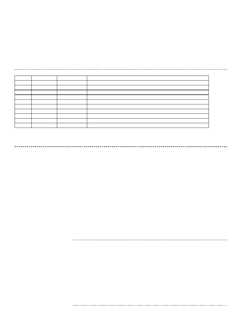
DETERMINE the type of gas control system from the Model or Serial No. Suffix on the unit rating plate:
Suffix
Where
Option
Gas Control System
None
N/A
AG1
Single Stage with Air Controller
-2
Model No.
AG3
Two Stage with Two-Stage Ductstat
-MV-7
Serial No.
AG30 or AG31
Maxitrol Series #14 Outside Air Only (Amplifier A1014U-00)
-MV-8
Serial No.
AG32
Maxitrol Series #14A Outside Air Only (Amplifier A1014U-00)
-MV-9
Serial No.
AG33
Maxitrol Series #44 Outside Air Only (Amplifier A1044)
-MV-B
Serial No.
AG36
Paint Spray Booth System (Maxitrol 94)
-MV-C
Serial No.
AG37
Maxitrol Series #DDC for Outside Air Only (Signal Conditioner)
-MV-D
Serial No.
AG47
Maxitrol Series #14 Outside Air and Recirculation (Amplifier ADFM14)
-MV-E
Serial No.
AG48
Maxitrol Series #44 Outside Air and Recirculation (Amplifier ADFM44)
-MV-F
Serial No.
AG51
Maxitrol Series DDC for Outside Air and Recirculation
For units with Maxitrol Series 14 or 14A, remove and individually tape wires from Terminals 4 & 8 on the amplifier
For units with Maxitrol Series 44, remove and individually tape wires from Terminals 2, 4 and 8 on the amplifier
For units with Maxitrol Series DDC, the customer provided input signal must be 4-20 milliamps (conditioner dip switch "on") or
0-10 volt DC (conditioner dip switch "off")
3. Check pilot and burner ignition and pilot operation (hot surface ignition)
Turn the disconnect switch ON. Turn blower service switch and burner service switch to TEST position.
2. Measure burner differential air pressure (cont'd)