0 electrical supply and wiring (cont'd) – Reznor RDF Unit Installation Manual User Manual
Page 18
I-RDF, PN148384R5, Page 18
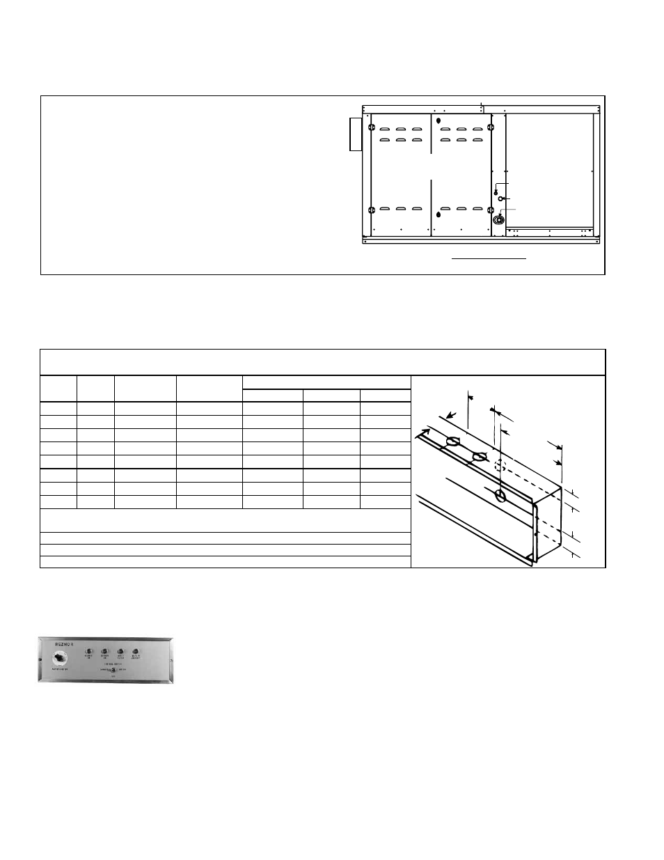
Control Side
Control
Compartment*
Blower
Compartment
Supply Wiring**
24V Wiring**
Gas Supply
FIGURE 14 - Location of Gas
Connection, Electrical Supply
Connection, and Control Wiring
Connections on RDF Series 3
Direct-Fired Systems
NOTES:
* RDF-2 and RDF-3 Series 3 systems have double hinged
doors as illustrated. Control compartment on RDF-1 Series 3
systems has a single hinged door.
** Configuration shown is for RDF-2 and RDF-3 Series 3. The
supply connection on the RDF-1 Series 3 systems is above
the control wiring connection.
Disconnect
Switch
Location
FIGURE 15 - Remote
Console Dimensions
2-3/8
(60)
6 (152)
5-15/32 (139)
1-5/16 (33)
1-3/32 (28)
4-7/16
(113)
1-3/32 (28)
Locations of Knockout
Holes (dimensions to
centerlines)
Technical Data of the Remote Console (Variations depend on options selected; consult custom wiring diagram
for controls and to determine wiring required.)
Control
Switch
Qty of
Lights*
Temperature
Selector**
Potentiometer
***
Dimensions - inches (mm)
L****
H****
D
Yes
3
Yes
No
10-3/4 (273) 7-5/8 (194) 2-5/8 (67)
Yes
3
No
No
10-3/4 (273) 7-5/8 (194) 2-5/8 (67)
Yes
3
Yes
Yes
15-3/4 (400) 7-5/8 (194) 2-5/8 (67)
Yes
3
No
Yes
10-3/4 (273) 7-5/8 (194) 2-5/8 (67)
Yes
4
Yes
No
15-3/4 (400) 7-5/8 (194) 2-5/8 (67)
Yes
4
No
Yes
15-3/4 (400) 7-5/8 (194) 2-5/8 (67)
Yes
4
Yes
Yes
15-3/4 (400) 7-5/8 (194) 2-5/8 (67)
Yes
4
No
No
15-3/4 (400) 7-5/8 (194) 2-5/8 (67)
* 3 - Blower On, Burner On, and Safety Lockout on both RC13 and RC14; 4th light is
Dirty Filter Indicator on Option RC14 only
** On the console with Gas Control Options AG 31, 32, 33, 47, or 48
*** On the console with Air Control Options AR19 or AR22
**** Subtract 1" (25mm) when recessing
Dirty Filter Light
FIGURE 16 - Option
RC14 with Dirty
Filter Light and
Potentiometer
7.0 Electrical
Supply and
Wiring (cont'd)
Control Wiring (cont'd)
there is a brief description of the optional electrical controls used for airflow. Refer to
the operation manual, Form O-ADF/RDF, for additional control information.
Remote Console
If ordered, the optional remote console is shipped separately. Remote consoles include
terminal blocks for wiring. Depending on what gas control or inlet air options were
ordered, the console could include a temperature selector and/or a potentiometer. If
a dirty filter switch is ordered the indicator light is on the console. See
FIGURE 15 for
console size.
When a console with a dirty filter indicator is selected, the remote console includes a
fourth light (dirty filter indicator light). The light is activated by an adjustable, single-
pole/normally open differential pressure switch that senses air pressure across the
filter bank. There are field-installation procedures that must be done for the proper
operation of the dirty filter indicator light.
Dirty Filter Light Installation Instructions
Before the system is operating, connect the sensing tubes from the switch
to their sensing locations in the field-installed filter cabinet. (Cabinet installation
instructions are in Paragraph 6.2.)
1) Run the tubes through the holes in the cabinet wall. Pull gently to extend the
tubing to its entire length without stress.
2) Position the tubing approximately at the center of the height of the filter rack.
3) Identify the tube connected to the positive connection on the switch (
FIGURE
17) as the positive pressure tube. Determine the length of tubing required to
attach the
positive pressure tube so that it will sense pressure at the inlet
side of the filter rack.
Identify the tube connected to the negative connection on the switch (
FIGURE
17) as the negative pressure tube. Determine the length of tubing required to